Hi folks,
My first post on here (although long time lurker) and my first Amp build.
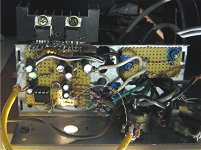
Dual Mono Power Amp with 300VA torroids
Audiosector LM3875
HiFi2000 enclosure with Onzow illuminated switches
And I'll offer a big "Thank You" to Peter Daniels for all his help via email while I was putting this together.
My first post on here (although long time lurker) and my first Amp build.
Dual Mono Power Amp with 300VA torroids
An externally hosted image should be here but it was not working when we last tested it.
Audiosector LM3875
An externally hosted image should be here but it was not working when we last tested it.
HiFi2000 enclosure with Onzow illuminated switches
An externally hosted image should be here but it was not working when we last tested it.
And I'll offer a big "Thank You" to Peter Daniels for all his help via email while I was putting this together.
Wow!!!
WOW!!!, great quality construction!
Hi folks,
My first post on here (although long time lurker) and my first Amp build.
Dual Mono Power Amp with 300VA torroids
Audiosector LM3875
HiFi2000 enclosure with Onzow illuminated switches
And I'll offer a big "Thank You" to Peter Daniels for all his help via email while I was putting this together.
WOW!!!, great quality construction!
Hi folks,
My first post on here (although long time lurker) and my first Amp build.
Dual Mono Power Amp with 300VA torroids
An externally hosted image should be here but it was not working when we last tested it.
"shorted turn" alert!
google that concept and remove that yellow wire. that's not a place to tap into chassis!
"shorted turn" alert!
google that concept and remove that yellow wire.
that's not a place to tap into chassis!
No need for Google. There's no complete circuit around the core of the transformer and hence no shorted turn.
I do take the point that there's no need to earth at that point though.
It was just a handy spot to use during the build and testing when parts were being moved around. I have a much more appropriate and neater location for that chassis connection in mind.
")
Hi Howlindawg,
I like your AC in cable. What is it and who is the source?
Hi Bob,
The mains cable is Mark Grant DSP 2.5.
Three core 2.5 double shielded mains cable.
>Website<
No need for Google. There's no complete circuit around the core of the transformer and hence no shorted turn.
I do take the point that there's no need to earth at that point though.
It was just a handy spot to use during the build and testing when parts were being moved around. I have a much more appropriate and neater location for that chassis connection in mind.
If that yellow wire connects directly to the chassis somewhere at its far end, it's a shorted turn. Otherwise, whatever it's connected to has a one-turn secondary in series with it and ground, and is getting one turn's worth of AC voltage from the transformer.if you are deriving ground from the mounting bolt on top, it is a shorted turn.
it may not be as very bad one but it still meets the def, I think.
just wanted to point it out. other than that, I like the layout a lot.
I'd even want to put an insulator (at least electrical tape, or maybe something more elegant that matches the rest of this thing) over the threads and that plate so I wouldn't be tempted to use it as a temporary ground for a meter probe (or put a sticker on each one saying "Not A Ground"). There's surely measurable AC between the top of that thread and any chassis connection.
The other end of the wire is isolated from the chassis.
But like I said in an earlier post, I'll move it.
I'll relocate those earths to posts beneath the boards.
There's no good reason that it's connected there other than convenience when parts were being moved around during the construction.
I must admit that I hadn't considered that. Thanks!
Thanks for all the comments folks. Compliments and constructive criticism are equally appreciated.
But like I said in an earlier post, I'll move it.
I'll relocate those earths to posts beneath the boards.
There's no good reason that it's connected there other than convenience when parts were being moved around during the construction.
Otherwise, whatever it's connected to has a one-turn secondary in series with it and ground, and is getting one turn's worth of AC voltage from the transformer.
I must admit that I hadn't considered that. Thanks!
Thanks for all the comments folks. Compliments and constructive criticism are equally appreciated.


- Home
- Amplifiers
- Chip Amps
- Chip Amp Photo Gallery