Now complete.
Sound is satisfactory.
New image.
Video (regular camera).
YouTube - MOV01516.
YouTube - MOV01522.
YouTube - MOV01521.
Sound is satisfactory.
New image.
Video (regular camera).
YouTube - MOV01516.
YouTube - MOV01522.
YouTube - MOV01521.
Attachments
And BTW, you don't really need those high wattage resistors. You could even get away with 125mw resistors.
")
Starting by 4 ohm loads support is a good reasonI understand what you are saying
One question... why are you using LM3886, and not LM3875?
Looks Pro-Built....
Looks Pro-Built, and if it had been, man, would have it been expensive!!! Great job!
Hello everybody,
This is my new system. LME49830 + MOSFET output stage. MOS PA.
...snipped IMG's...
Looks Pro-Built, and if it had been, man, would have it been expensive!!! Great job!
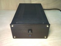
My first DIY amplifier
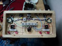
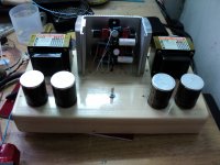
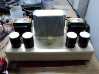
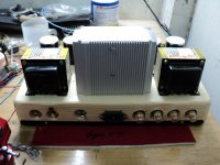
Finally completed my first amplifier. Learned a lot from this forum. Thanks a lot.
Circuit diagram is from LM4780 datasheet Fig5, I just modified it a little bit.
Grounding topology is also from LM4780 datasheet, see the ref broad composite layer. But I don't have the 2R7 between the signal ground star and the power ground star. Pin7 is connected to the power ground star.
At some point the audio ground must be connected to the mains ground. I use “The power amp design handbook 5th edition” fig18.1 as my reference. Together with the ESP disconnected network(with 100R resistor), the amplifier is hum free in a CAS system at full volume. However if the power ground star is connected to the mains ground via the disconnected network, when I turn the volume control beyond 3 o'clock position, at the speaker terminal I measured 0.1mVac (measured by a Fluke 77) and I can hear the hum about 1 feet away from the speaker. This is the most difficult part of the project.
Attachments


my first post at DIYaudio
Amplifier on 2xtda7294 and power supply on IR2153.
I love traaaance
Welcome to the forum. You could post bigger than thumbnails though. Loving trance the kaZantip style parties?
*medium size ones you changed look better. Cool decoration.
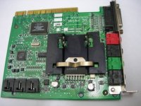
LM3886-To-STK Retrofit
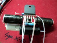
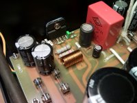
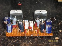
Hi Guys, a solder joint on the muting resistor in the right channel of my LM3886-to-stk retrofit board in my Technics SA-350 popped loose and since I had the unit open, any way, and have a new Canon A430 to take detailed pictures with, I decided to go for it and post some more detailed pictures of the board. I'm still planning on having FAR Circuits run some of these retrofits and some simplified, low cost, VinyLiberator preamp boards late summer or early fall, when my finances are better.
Hi Guys, a solder joint on the muting resistor in the right channel of my LM3886-to-stk retrofit board in my Technics SA-350 popped loose and since I had the unit open, any way, and have a new Canon A430 to take detailed pictures with, I decided to go for it and post some more detailed pictures of the board. I'm still planning on having FAR Circuits run some of these retrofits and some simplified, low cost, VinyLiberator preamp boards late summer or early fall, when my finances are better.
Attachments
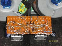
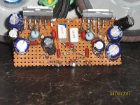
At Home
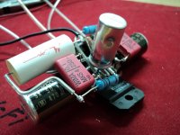
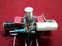
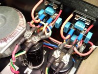
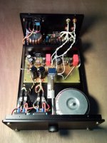
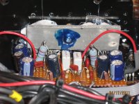
Here are a couple shots of the retrofit, installed in the Technics SA350. It's looking a little better, now that I've cleaned off the excess thermal compound and tidied up the input circuit!
Here are a couple shots of the retrofit, installed in the Technics SA350. It's looking a little better, now that I've cleaned off the excess thermal compound and tidied up the input circuit!
Attachments
Hedged My Bet
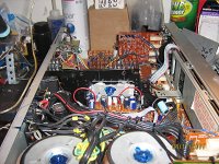
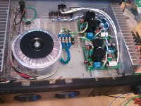
Absolutely! It even idled quite warm on the stock +/- 42V rails, but I hedged my bet by going to a pair of salvage 123VA toroids, upping the stock 8200uf (I think) filter caps to 15,000uf, and ending up at a nice, stiff +/- 33V. I play it loud, but bedroom use and a lossy crossover, with series summing resistors in the subwoofer channel, keep the amps out of thermal shutdown. It has the sound that LM3886's are famous for!
I'm lazy, have an ego complex, and want to make boards available for other DIY retrofitters, so I'll have FAR Circuits do 'em in a few months, then blank boards will be in FAR's catalog in less than a year from my initial order! My design is to have snubbers for remote power supply operation and extra pads in the input area for subsonic/ultrasonic filter components.
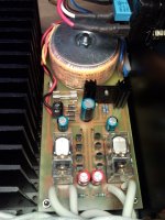
That little heatsink for two 86es scares me... Nice retrofit, now to get you to start etching some boards
Absolutely! It even idled quite warm on the stock +/- 42V rails, but I hedged my bet by going to a pair of salvage 123VA toroids, upping the stock 8200uf (I think) filter caps to 15,000uf, and ending up at a nice, stiff +/- 33V. I play it loud, but bedroom use and a lossy crossover, with series summing resistors in the subwoofer channel, keep the amps out of thermal shutdown. It has the sound that LM3886's are famous for!
I'm lazy, have an ego complex, and want to make boards available for other DIY retrofitters, so I'll have FAR Circuits do 'em in a few months, then blank boards will be in FAR's catalog in less than a year from my initial order! My design is to have snubbers for remote power supply operation and extra pads in the input area for subsonic/ultrasonic filter components.
Lol, that rev C is a way underutilisation of that carver case.
Only if the meters are not hooked up! If they are, it's completely awesome!
- Home
- Amplifiers
- Chip Amps
- Chip Amp Photo Gallery