Hi Andrew.
To get a better view than these pictures I would have to pull the amp apart, not my idea of a good weekend. The power supply that that these parts are taken from spent years plugged into a wall with no problems. If these parts are rated to 400V and are safety approved parts why would there be any problem using them with a 300V transformer?
To get a better view than these pictures I would have to pull the amp apart, not my idea of a good weekend. The power supply that that these parts are taken from spent years plugged into a wall with no problems. If these parts are rated to 400V and are safety approved parts why would there be any problem using them with a 300V transformer?
Thanks, Wim.very nice work ~D'Evil~ SPb -, and not only the electronics. I see you make very good photo's also. What kind of camera you use?
Just 3.2Mpx Canon Powershot A75
")
Hi Andrew
This capacitor thing is getting very technical, nice to know we are all very safety conscious.
Have a look at this and lets us know what you think.
http://my.execpc.com/~endlr/line-filter.html
(first hit that came up at google and I only had a quick look at the article)
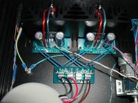
I notice from the pictures the blue things (ceramic) 2200pf (0.0022uf) are X1 Y2 (impulse tested to 4 & 5 kV) higher than X2?
Note X1 and X2 are usually film used across L & N while Y1 & Y2 are usually ceramic for L & N to ground limited to a maximum of 4700pf as leakage above this value and an earth failure could could result in an electric shock.
I'm off now to look for a paper on the whole mains capacitor safety standards thing.
Regards to all.
Greg
This capacitor thing is getting very technical, nice to know we are all very safety conscious.
Have a look at this and lets us know what you think.
http://my.execpc.com/~endlr/line-filter.html
(first hit that came up at google and I only had a quick look at the article)
I notice from the pictures the blue things (ceramic) 2200pf (0.0022uf) are X1 Y2 (impulse tested to 4 & 5 kV) higher than X2?
Note X1 and X2 are usually film used across L & N while Y1 & Y2 are usually ceramic for L & N to ground limited to a maximum of 4700pf as leakage above this value and an earth failure could could result in an electric shock.
I'm off now to look for a paper on the whole mains capacitor safety standards thing.
Regards to all.
Greg
AndrewT said:as soon as anyone enters DIYanything, one must know the risks and how to minimise them. Anything else is criminal.
Absolutely, positively correct!!
It is each builders responsibility to KNOW before they build. Mains voltages and tube supplies can kill instantly. Caps popping in your face can blind and disfigure.
Safety first, ALWAYS.
If in doubt, ask questions. Plenty of good people here who will answer. This is a great forum and we are lucky to have it.
I agree with you all with reguards to safty. I did not know that the caps on the mains where the right ones for this project. I just assumed that they would be ok as they worked well in this role previously. This could be very risky.
As for the moment should I pull them out?
As for the moment should I pull them out?
Mike-Toronto said:
As for the moment should I pull them out?
They are properly rated - leave them in.
I had decided to take the time to read through this today as I had more time as I do during the week. Thank you all for the feedback and information. Since building this project I have become much more interested in building other kits. I am in no hurry and will take some time to get a better understanding of basic electronics. In regards to the caps on the MAINS. I did know enough to understand why the caps where there. I have been working with professional audio equipment for over a decade now and have dealt with several power conditioners. This being said I do not have the slightest clue as to what most of the information on the parts mean.
All of you have helped drive the safety nail further into my way of thinking. It is not just me that I am putting in harms way.
All the best
Mike
All of you have helped drive the safety nail further into my way of thinking. It is not just me that I am putting in harms way.
All the best
Mike
VLSI, if you have not found another resource on X-Y caps look here:
http://www.justradios.com/safetytips.html
When I restore old radios I add a 3 wire cord and a X-Y cap.
http://www.justradios.com/safetytips.html
When I restore old radios I add a 3 wire cord and a X-Y cap.
Hi Guys!
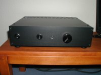
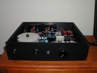
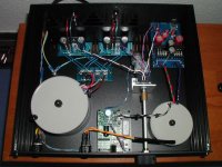
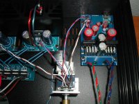
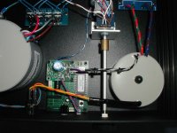
Jumping in here into the current discussion with my recent finished project, a gainclone with integrated usb-dac and remotable volume control. This unit works and plays absolutely great! A bit more about the sound after a proper break-in period...
A brief description:
Amps: AudioSector GainClone LM3875 Basic Kit
DAC: AudioSector USB-DAC with TDA1543
Transformers: Thel Audio, fully encapsulated
(for DAC part: 50VA, 2x9V, with additional windings of 2x3V, connected to 1x6V for powering the Alps remote control unit to drive the motor pot; for amp part: 250VA, 2x24V.)
Remote Control Unit: Alps IRFB4 (with additional small pcb on top to rectify AC from trans to DC)
Volume Pot: Alps blue pot, motorized, 50kohm log
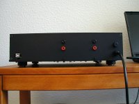
Chassis: Galaxy 1GX388 from Autocostruire, Italy
The unit has two power switches to power on DAC section and AMP section separately, so there is no on/off switching noise when the dac part is powered on prior to the amp part. Further more the dac part could always be switched on for best performance, even if the amp part has to be switched off for any reason (e.g. trying out some new speaker cables).
This is a no-compromise-solution because there is a usb input ONLY. But my notebook is my only source, and this way the signal has a very short way with no switches in line except the pot.
Feets are two pairs of Soundcare spikes!
Here are some pics, if they aren't too large...
Happy listening!
martin
Jumping in here into the current discussion with my recent finished project, a gainclone with integrated usb-dac and remotable volume control. This unit works and plays absolutely great! A bit more about the sound after a proper break-in period...
A brief description:
Amps: AudioSector GainClone LM3875 Basic Kit
DAC: AudioSector USB-DAC with TDA1543
Transformers: Thel Audio, fully encapsulated
(for DAC part: 50VA, 2x9V, with additional windings of 2x3V, connected to 1x6V for powering the Alps remote control unit to drive the motor pot; for amp part: 250VA, 2x24V.)
Remote Control Unit: Alps IRFB4 (with additional small pcb on top to rectify AC from trans to DC)
Volume Pot: Alps blue pot, motorized, 50kohm log
Chassis: Galaxy 1GX388 from Autocostruire, Italy
The unit has two power switches to power on DAC section and AMP section separately, so there is no on/off switching noise when the dac part is powered on prior to the amp part. Further more the dac part could always be switched on for best performance, even if the amp part has to be switched off for any reason (e.g. trying out some new speaker cables).
This is a no-compromise-solution because there is a usb input ONLY. But my notebook is my only source, and this way the signal has a very short way with no switches in line except the pot.
Feets are two pairs of Soundcare spikes!
Here are some pics, if they aren't too large...
Happy listening!
martin
Attachments
- Home
- Amplifiers
- Chip Amps
- Chip Amp Photo Gallery