I was thinking that for my next system / remote, I'd add the ability to display (volume, CD tracks, station, etc) on the remote itself. You can get relatively inexpensive TFT panels now. Carve a nice case, a little firmware, rechargeable batteries, and perhaps I have something.
otoh, smart phones and tablets are the 'new hot thing' these days.
I would consider some way to have a web back-end be the way into your system (or one way in). on my project I picked simple rs232 serial and have a simple protocol for the remote to send cmds and queries in via serial. this works for both the xbee style remote AND also an apache webserver on some linux box, somewhere (could even be a one board plug-style/marvell ARM board).
then you can spend the rest of your time doing android and ios apps for your stereo (I'm only half kidding, too).
I think all my new projects will be split 'in half' and have a serial connection between client and server, just to be able to have multiple management ways 'in' to the box. IR is cheap and easy; but a serial back-end gives a lot of fancy 2-way utility.
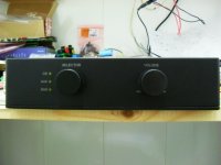
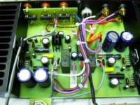
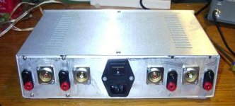
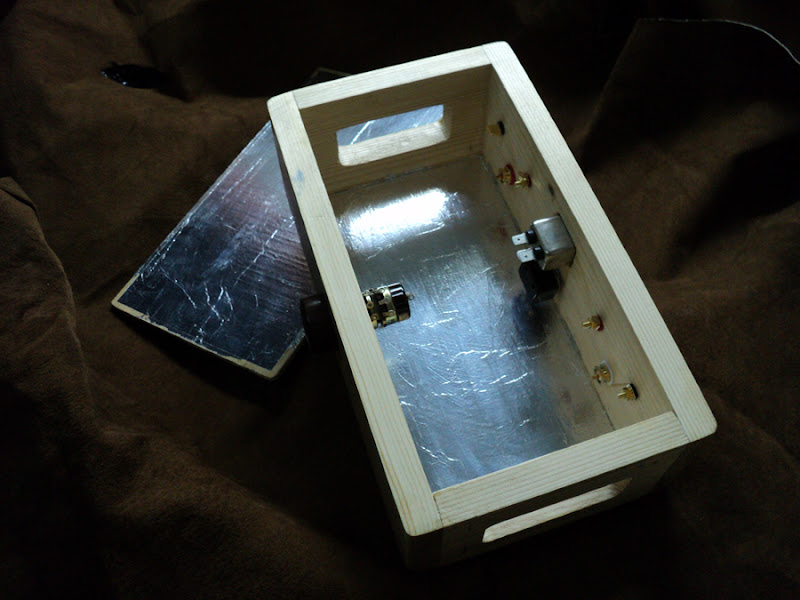
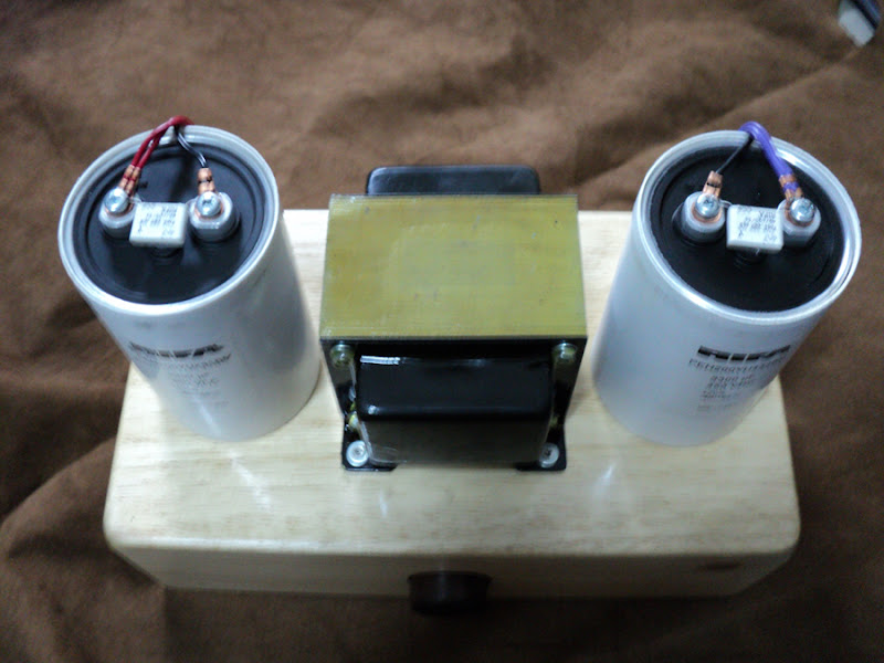
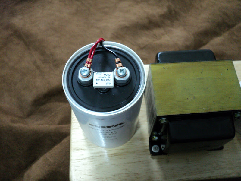
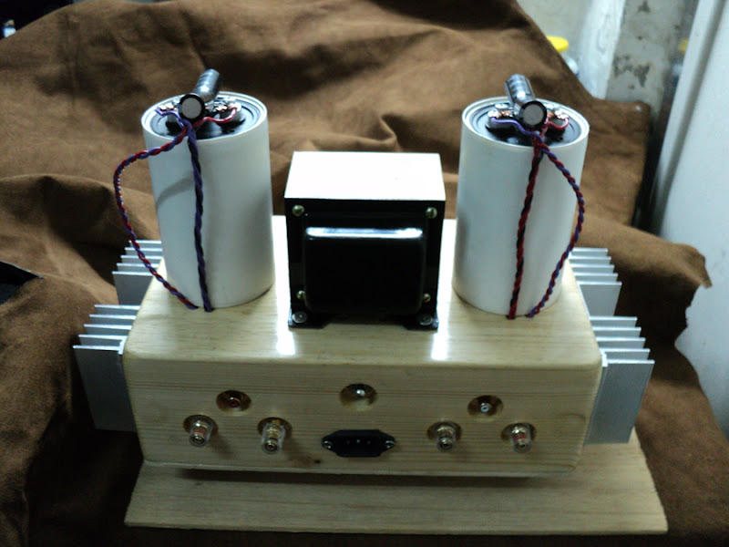
Hi! My PA-100 prototype with separate power supply =)
Attachments
-
 resizefront.jpg86.6 KB · Views: 2,141
 -
 resizerear.jpg109.7 KB · Views: 2,073
 -
 resizerear2.jpg111.1 KB · Views: 1,985
 -
 resizetop3.jpg125.4 KB · Views: 605
 -
 resizetop2.jpg135 KB · Views: 1,917
 -
 resizetop.jpg121.9 KB · Views: 1,973
 -
 resizeselector.jpg108.4 KB · Views: 551
 -
 resizetop4.jpg112.7 KB · Views: 504
 -
 resizetop5.jpg123.6 KB · Views: 514
Hi! My PA-100 prototype with separate power supply =)
It's really nice to see a truely DIY project using your own PCB's etc.
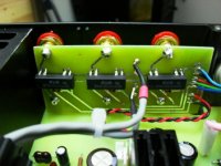
I always hate to see heat-sinks inside boxes though :-(
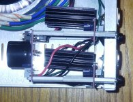
Looks like a sealed diecast box?
Frank
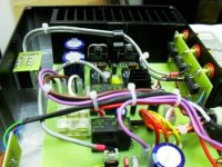
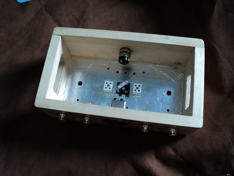
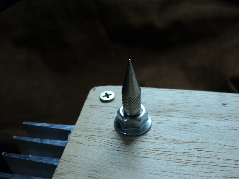
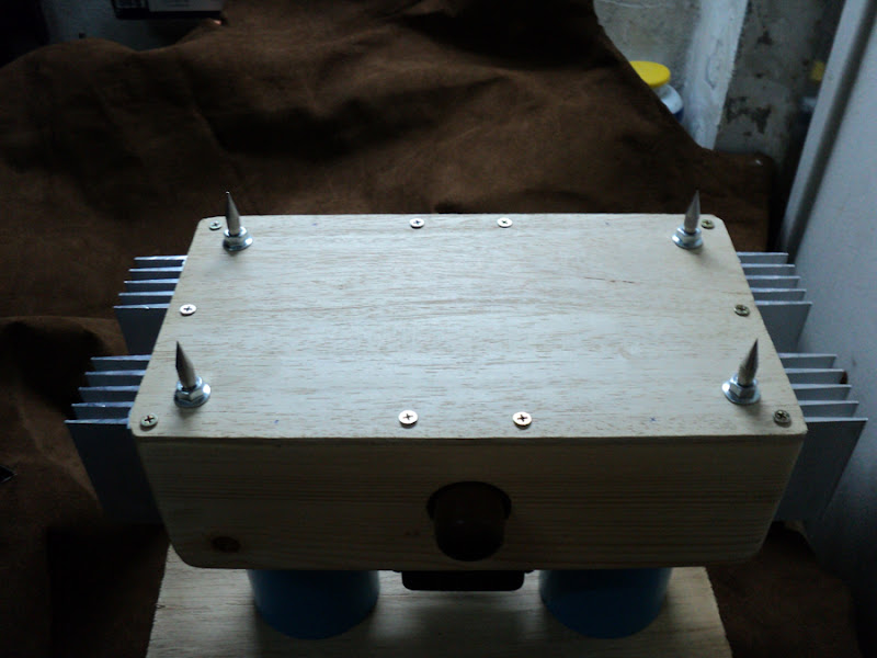
Hi! Yes this is aluminium diecast box. Heatsinks are densely pressed to box walls and the box serves as heatsink continuation with the big area. I can drill holes but i dont like dust in the case =)It's really nice to see a truely DIY project using your own PCB's etc.
I always hate to see heat-sinks inside boxes though :-(
Looks like a sealed diecast box?
Frank
Hi! My PA-100 prototype with separate power supply =)
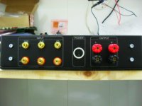
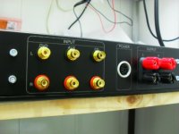
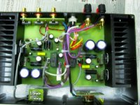
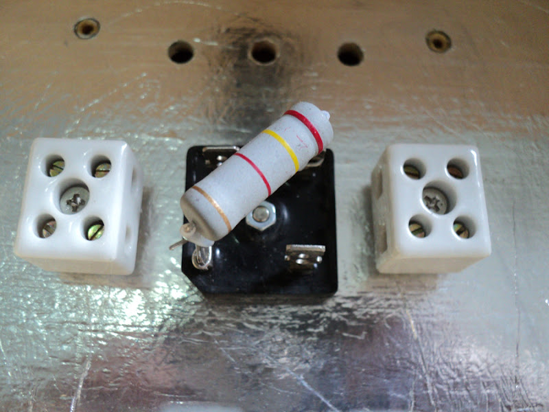
Great Build! I like the fact that the PCBs are built on the volume control, source selector, and the RCA inputs - ensures neat wiring. May I know what chip you are using on the RCA inputs for source selection? Or is it a relay?
Last edited:
This is 12V reed relay EDR302A1200Great Build! I like the fact that the PCBs are built on the volume control, source selector, and the RCA inputs - ensures neat wiring. May I know what chip you are using on the RCA inputs for source selection? Or is it a relay?
Great Build! I like the fact that the PCBs are built on the volume control, source selector, and the RCA inputs - ensures neat wiring.
I agree, the layout is well executed.

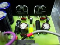
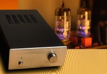
My little HybridAMP
Here's my little project
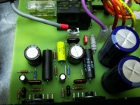
On power board.
IC: LM3886T
Resistor: (all) Takman 1/2w Metal Film
Capacitor Elc: 3x 100µF/50V Elna Cerrafine, 2x 22µF/50V Nichicon
Capacitor: 2x 100nF/250V Wima MKP10
Capacitor Coupling (DC Blocking): 2x 1.5µF/400V MKP Solen (Original)
Capacitor Power Supply: Nover AudioGrade 4x 6800µF/50V
Potentiometer: Alps Blue Beauty
PCB: XY HiFi (Dual Layer Fiber Board)
On tube buffer board (based MF X10D)
Tube: 6BQ7 + Octal Socket
Resistor: Takman Carbon, Allen Bradley, Riken, Standar Metal Film (1% Tolerance)
Capacitor Elc: 2x Panasonic FC Blue 2200µF/25V, 8x Nichicon Gold 1000µF/35V, 2x Nichicon Muse BP 10µF/50V
Capacitor: 4x ERO 220n/250V MKC1862, 2x Soshin 220pF Silver Mica
Capacitor Coupling (DC Blocking): 2x Siemens 3.3µF/100V
Capacitor PowerLine Filter: RIFA X2 100nF/275VAC
Diode: 5x Vishay BYV26E Ultra Fast Avalanche Sinterglass Diode
PCB: Lite Audio (Single Layer Fiber Board)
Hope you like it......
Here's my little project
On power board.
IC: LM3886T
Resistor: (all) Takman 1/2w Metal Film
Capacitor Elc: 3x 100µF/50V Elna Cerrafine, 2x 22µF/50V Nichicon
Capacitor: 2x 100nF/250V Wima MKP10
Capacitor Coupling (DC Blocking): 2x 1.5µF/400V MKP Solen (Original)
Capacitor Power Supply: Nover AudioGrade 4x 6800µF/50V
Potentiometer: Alps Blue Beauty
PCB: XY HiFi (Dual Layer Fiber Board)
On tube buffer board (based MF X10D)
Tube: 6BQ7 + Octal Socket
Resistor: Takman Carbon, Allen Bradley, Riken, Standar Metal Film (1% Tolerance)
Capacitor Elc: 2x Panasonic FC Blue 2200µF/25V, 8x Nichicon Gold 1000µF/35V, 2x Nichicon Muse BP 10µF/50V
Capacitor: 4x ERO 220n/250V MKC1862, 2x Soshin 220pF Silver Mica
Capacitor Coupling (DC Blocking): 2x Siemens 3.3µF/100V
Capacitor PowerLine Filter: RIFA X2 100nF/275VAC
Diode: 5x Vishay BYV26E Ultra Fast Avalanche Sinterglass Diode
PCB: Lite Audio (Single Layer Fiber Board)
Hope you like it......
Attachments
Very impressive work, High-End look =)Here's my little project
On power board.
IC: LM3886T
Resistor: (all) Takman 1/2w Metal Film
Capacitor Elc: 3x 100µF/50V Elna Cerrafine, 2x 22µF/50V Nichicon
Capacitor: 2x 100nF/250V Wima MKP10
Capacitor Coupling (DC Blocking): 2x 1.5µF/400V MKP Solen (Original)
Capacitor Power Supply: Nover AudioGrade 4x 6800µF/50V
Potentiometer: Alps Blue Beauty
PCB: XY HiFi (Dual Layer Fiber Board)
On tube buffer board (based MF X10D)
Tube: 6BQ7 + Octal Socket
Resistor: Takman Carbon, Allen Bradley, Riken, Standar Metal Film (1% Tolerance)
Capacitor Elc: 2x Panasonic FC Blue 2200µF/25V, 8x Nichicon Gold 1000µF/35V, 2x Nichicon Muse BP 10µF/50V
Capacitor: 4x ERO 220n/250V MKC1862, 2x Soshin 220pF Silver Mica
Capacitor Coupling (DC Blocking): 2x Siemens 3.3µF/100V
Capacitor PowerLine Filter: RIFA X2 100nF/275VAC
Diode: 5x Vishay BYV26E Ultra Fast Avalanche Sinterglass Diode
PCB: Lite Audio (Single Layer Fiber Board)
Hope you like it......
Last edited:
thanksVery impressive work, High-End look =)
")
and here is top view
An externally hosted image should be here but it was not working when we last tested it.
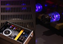
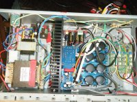
New project 3 way active amp.
It contrast to the previous post here's my messy 2nd budget project. I think I need a bigger case to get things tidy !!
Anyway amp includes 4 * lm3886 mono boards bought as pcb's and populated with decent parts.These power the bass and mid range.
HF driven by ready populated lm1875 stereo board.
Trafo 150w and case from defunct Sony surround amp bought off ebay for $20!Trafo runs 30v rails to lm3886 and 15v to lm1875.
Active crossover ESP project 09*2 with separate trafo and self built psu.
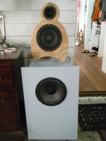
Sounds totally brilliant on my 3 way hybrid open baffle speakers. The sound quality stay's clear even when cranked up! Im definitley a convert to the active system.
It contrast to the previous post here's my messy 2nd budget project. I think I need a bigger case to get things tidy !!
Anyway amp includes 4 * lm3886 mono boards bought as pcb's and populated with decent parts.These power the bass and mid range.
HF driven by ready populated lm1875 stereo board.
Trafo 150w and case from defunct Sony surround amp bought off ebay for $20!Trafo runs 30v rails to lm3886 and 15v to lm1875.
Active crossover ESP project 09*2 with separate trafo and self built psu.
Sounds totally brilliant on my 3 way hybrid open baffle speakers. The sound quality stay's clear even when cranked up! Im definitley a convert to the active system.
Attachments
Last edited:
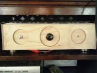
Another Chip Amp build thread
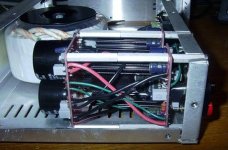
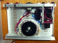
Yes, it's just another Chip Amp build, but it's my chip amp build. And it's my first one, so I'm really happy about it.
Yes, it's just another Chip Amp build, but it's my chip amp build. And it's my first one, so I'm really happy about it.
- It's the LM3886 kit from ChipAmp Electronics LLC, a.k.a. ChipAmp.com.
- The boards are mounted on the back plate, so there is minimal distance from the amplifier boards to in RCA jacks and speaker terminals. This keeps them away from the mains and transformer secondaries. I'm not sure if I would recommend this to anyone. It was very difficult to get the wires soldered into the board.
- Yes, the heatsinks are small, but I'm using it at moderate volume in a small home office. I would occasionally feel them, and they never felt more than warm. I can always add a fan or two later if needed.
- I left room on the left side for another power supply and 2 amp boards, and even attached RCA jacks and speakers terminals for when I decide to make it 4-channel bridgeable.
- The transformer has built-in shielding. Note the purple wire going to the star ground. It should be adequate for another 2 channels.
- The chassis is a mere 12" X 8" X 3.5" while still leaving room to double the channels. It's such a tight fit I had to file the edges of the PCB's!
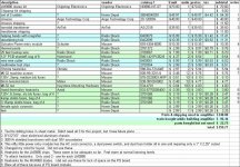
- I keep meticulous records of how much I spend on my audio projects. I've included my spreadsheet so anyone contemplating a similar build can get an idea of how much it will cost.
- The final verdict: I'm very happy with the sound. The bass is punchy, which others have said they've gotten from chip amps and very crisp, clear sound. It's dead quite too, not a hint of buzz or hum.
Attachments
lm 3886
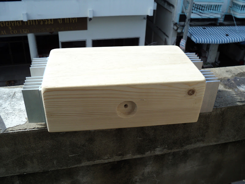
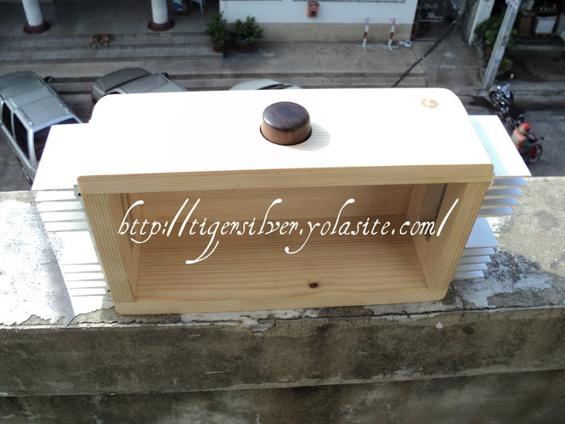
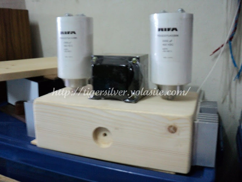
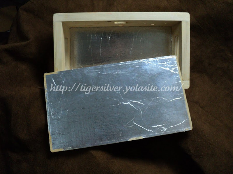

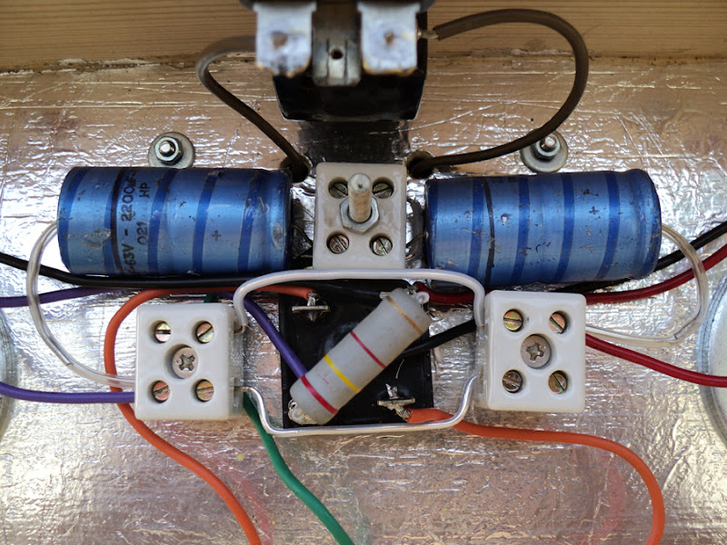
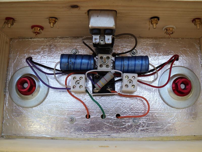
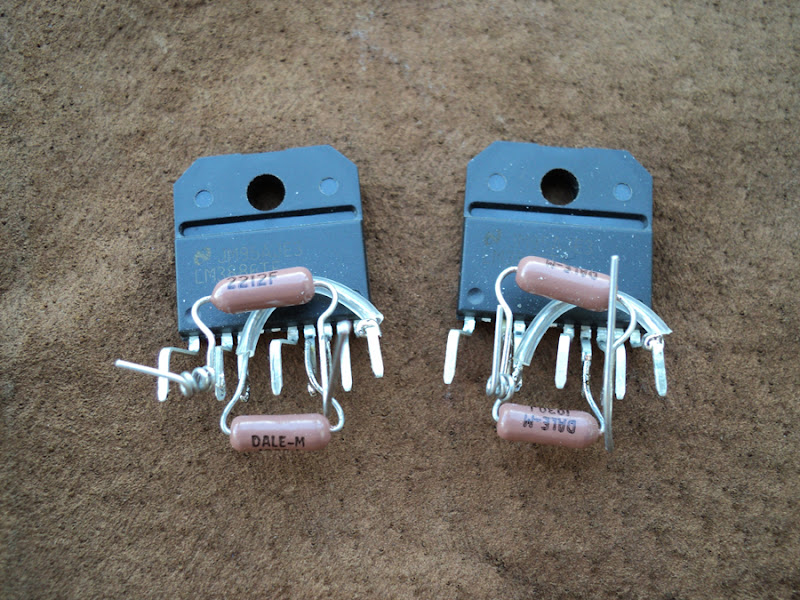
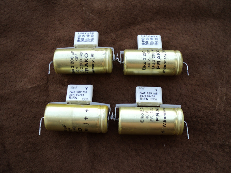
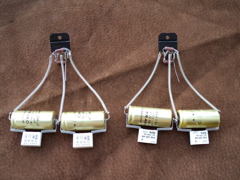
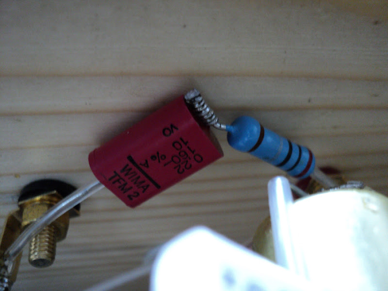


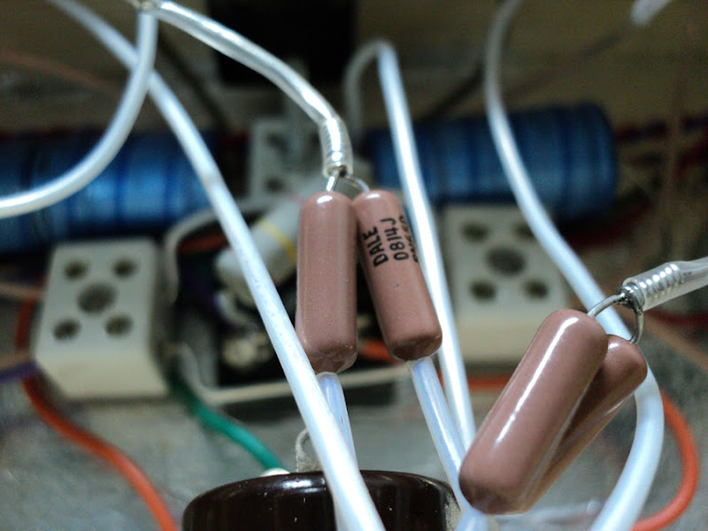
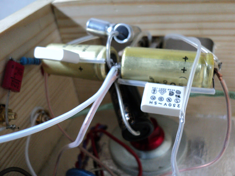
Too much bass as C rifa 0.0047.
Improved use Rubycon photo-flash 200uf help.
voice is more clear.
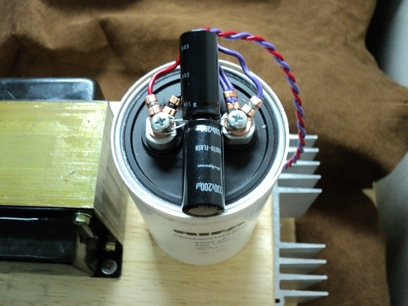
Outside to some minor adjustments, including cylinders C.
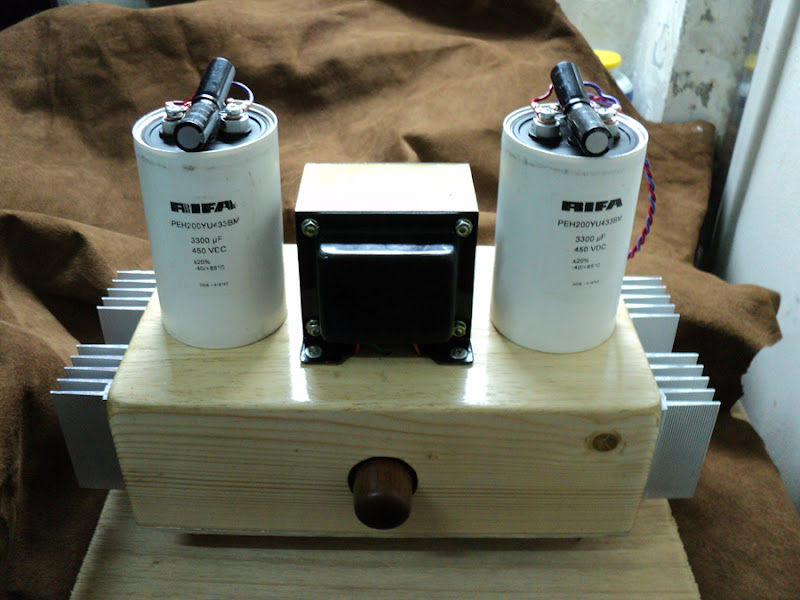
Now ... the sound overall is desirable, may be change about C rifa 4n7
---
If the wrong language. I'm sorry.
Too much bass as C rifa
0.0047.Improved use Rubycon photo-flash 200uf help.
voice is more clear.
Outside to some minor adjustments, including cylinders C.
Now ... the sound overall is desirable, may be change about C rifa
4n7---
If the wrong language. I'm sorry.
- Home
- Amplifiers
- Chip Amps
- Chip Amp Photo Gallery