Nice MOD job. What's funny is that I used to own a Technics SA-450 many years back. I'm curious as to what other modifications you are making to that receiver.
...snipped.../QUOTE]
Thanks for your interest. All the mods I wanted to do, to this point, have been done, so I'll list all of them.
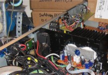
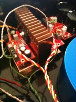
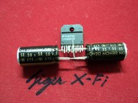
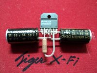
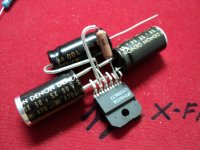
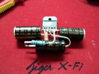
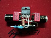
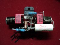
1) Replaced hard to find STK output DPP with a 2 X LM3886 board. I plan to have FAR circuits work me up a nice blank retrofit board for receivers. The LM3886 works perfectly over a huge range of supply voltages, so this board will be ideal for any receiver under 60W + 60W. The voltage amp and compu-drive boards weren't needed any more so they were removed.
2) Replaced original power transformer with a pair of 20.5-0-20.5V, 123VA toroids. The original ran warm, even without load, and the rails were +/- 42V, right at the top of the LM3886's range, causing them to idle too warm, as well. My new rails ended up at about +/- 33V and they don't go below +/-30V when the amps are pushed to audible clipping. Note about the heatsink: The sink is a little small for heavy-duty use, like sustaned high power drive into 4 ohms, as the STK's have larger heat transfer area and didn't need as large of a sink as a pair of LM3886's. A larger sink or low speed fan may be needed.
3) Filter capacitors are pretty inexpensive and nearly doubling to 15.000uf made for a nice-stiff power supply.
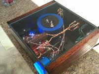
4) Since I'm a VLF Natural Radio enthusiast and enjoy monitoring lightning related signals (all audio frequency) and other whole Earth VLF events (note, nuclear detonations produce a 12khz burst!), I removed the VHF TV audio tuner, made obsolete by DTV, and replaced it with a VLF receiver board that uses the old TV Audio tuning control for a gain control.
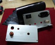
5) It's a real PIA to deal with the power cord when moving that SA350 into or out of the rack shelf, so I put an IEE computer-type power inlet on the SA350. Ground loop isolation is done with a pair of 6A rectifiers paralleled in opposite directions, bypassed by a 100ohm resistor and .1uf capacitor.
Picture: Lower left, near blue spot, ground loop isolator on IEE inlet. Bottom Right: 2 X LM3886 board. Top left, over In/Out RCA jacks, VLF Receiver board.
Attachments
My first project
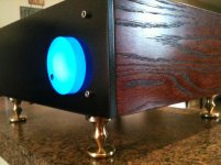
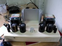
Hello guys. There is some very nice work on here! I got the diy audio bug and decided to build a Gainclone as my first serious project. I chose the LM3886 from chipamp.com.
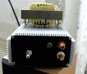
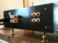
The case was made from .250 inch thick aircraft grade aluminum. The transformer cover was turned from T6 6061 aluminum. The sides are then covered with .750 thick red oak with a cherry stain. I machined the isolating feet from a bronze/copper alloy. The heatsink is machined from solid copper. The volume knob I cut from acrylic and then glass bead blasted for a frosted look.
I need to tidy up the wires still but overall I am happy with how it turned out.
I owe a huge thanks to everyone here for my inspiration!
Hello guys. There is some very nice work on here! I got the diy audio bug and decided to build a Gainclone as my first serious project. I chose the LM3886 from chipamp.com.
The case was made from .250 inch thick aircraft grade aluminum. The transformer cover was turned from T6 6061 aluminum. The sides are then covered with .750 thick red oak with a cherry stain. I machined the isolating feet from a bronze/copper alloy. The heatsink is machined from solid copper. The volume knob I cut from acrylic and then glass bead blasted for a frosted look.
I need to tidy up the wires still but overall I am happy with how it turned out.
I owe a huge thanks to everyone here for my inspiration!
Attachments
Hi Mud,
First.. thats awesome. I am really impressed!
Second I worry that you have made a shorted turn on your transformer and you will heat that sucker up. If you have a metal case for the transformer that touches a metal floor and then the metal bolt through the center you have created another turn on the transformer but its a never-ending turn.
Uriah
Thank you for the compliments! The transformer does not touch anything metal. It sits on 1/4" rubber and the bolt going thru center rest on a rubber washer as well. Is this not ok?
I was under the impression this was fine as long as everything was insulated. I have left the amp powered on for several hours at a time and no heat what so ever is generated from the torroid.
I was under the impression this was fine as long as everything was insulated. I have left the amp powered on for several hours at a time and no heat what so ever is generated from the torroid.
Thank you for the compliments! The transformer does not touch anything metal. It sits on 1/4" rubber and the bolt going thru center rest on a rubber washer as well. Is this not ok?
I was under the impression this was fine as long as everything was insulated. I have left the amp powered on for several hours at a time and no heat what so ever is generated from the torroid.
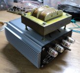
It doesn't matter whether the transformer is insulated, rather it depends if there is a current loop around the transformer formed by the shield/bolt/case combination. If you just hold a closed loop of wire around a toroidal transformer, a current will flow. If you are sure the bolt doesn't make electrical contact with the case, you should be fine.
It looks like you have a non-conducting/insulating lid on the amplifier.
It also looks like you have a support between the retaining plate and your lid.
NO PROBLEM.
But if you change the lid to conducting material then that support must be changed to non-conducting. Otherwise the metal support could make the shorted turn.
It also looks like you have a support between the retaining plate and your lid.
NO PROBLEM.
But if you change the lid to conducting material then that support must be changed to non-conducting. Otherwise the metal support could make the shorted turn.
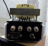
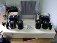
machined the isolating feet from a bronze/copper alloy. Volume knob from acrylic and glass bead blasted for a frosted look.
Truly pretty feet, love the personalised creativity bug.
Sunk-in back and front panels ? Too much time on your hands ?

(daddy P is a good instruction manual for neat wiring)
Last edited:
Torrence... AndrewT....
Thank you for making the transformer issue a little more clear. I think I will make a new cover out of a plastic just to be sure. The bolt is insulated from the case and yes the top of the case is acrylic.
Jacco... I built the amp over the course of several months. Even though this was my first serious audio project, I took my time to try to and make the amp look as good as it sounds.
Thank you very much. This is the next project to be done offline.love it!
Attachments
Truly pretty feet, love the personalised creativity bug.
Sunk-in back and front panels ? Too much time on your hands ?
(daddy P is a good instruction manual for neat wiring)
jacco, can you clarify this comment? What is daddy P?
Hello guys. There is some very nice work on here! I got the diy audio bug and decided to build a Gainclone as my first serious project. I chose the LM3886 from chipamp.com.
The case was made from .250 inch thick aircraft grade aluminum. The transformer cover was turned from T6 6061 aluminum. The sides are then covered with .750 thick red oak with a cherry stain. I machined the isolating feet from a bronze/copper alloy. The heatsink is machined from solid copper. The volume knob I cut from acrylic and then glass bead blasted for a frosted look.
I need to tidy up the wires still but overall I am happy with how it turned out.
I owe a huge thanks to everyone here for my inspiration!
Looks very nice.
Can't see any openings for air flow. I hope you are not relying purley on radiation and conduction to move the heat out from the chassis
")
Thank you very much
I'm do it , because I like wich wood.
Buttons adjust the tamarind wood .
Near finished now.
when finished , I'm show picture agian
The language used .. may not be quite.
About language, I 'm not good
I use google help
Thank you very much. agian
I'm do it , because I like wich wood.
Buttons adjust the tamarind wood .
Near finished now.
when finished , I'm show picture agian
The language used .. may not be quite.
About language, I 'm not good
I use google help
Thank you very much. agian
Attachments
Last edited:
LM3886I understand what you are saying
One question... why are you using LM3886, and not LM3875?
Easy to buy in Thailand
And I need a higher power.
In a call - out.
I use the bare wire of 99.99% silver.
To increase transparency Of music
Now complete.
Add new photos soon.
---------------------.
Hello everybody,
This is my new system. LME49830 + MOSFET output stage. MOS PA.
This is my new system. LME49830 + MOSFET output stage. MOS PA.
An externally hosted image should be here but it was not working when we last tested it.
An externally hosted image should be here but it was not working when we last tested it.
An externally hosted image should be here but it was not working when we last tested it.
- Home
- Amplifiers
- Chip Amps
- Chip Amp Photo Gallery