Harolda/Fatihkarali,
Some fine looking kit.
There truly are some talented people on this forum.
Chris.
I agree!!
Great work guys!
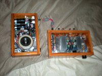
My now ~8yr old 6 channel DAC + bridged gainclone amp...
Still works perfectly
My design & home made double sided PCBs.
#1
#2
#3
#4
#5
Still works perfectly
My design & home made double sided PCBs.
#1
An externally hosted image should be here but it was not working when we last tested it.
#2
An externally hosted image should be here but it was not working when we last tested it.
#3
An externally hosted image should be here but it was not working when we last tested it.
#4
An externally hosted image should be here but it was not working when we last tested it.
#5
An externally hosted image should be here but it was not working when we last tested it.
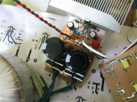
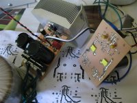
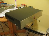
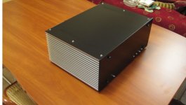
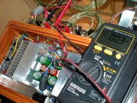
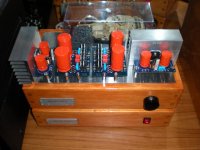
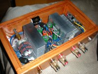
My new transconductance chipamp
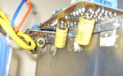
My CCS singled-ended class A MOSFET amp got me searching for an alternative that was equally simple but a little cheaper to build. The cost of large transformers, big caps, and huge heatsinks seems to add up pretty quick. My search led me to current-drive.info where a very simple current feedback method is described. The vetting of Esa's book can be found here. (I bought a copy.)
Rod Elliot describes essentially the same thing in Project 56 but actually explicitly states that the current drive system I'm using "should never be used in practice" for stability and interference concerns. From Esa's accounting and my prototyping experience I can say that the zobel on the output is mandatory. Without it I had some low frequency instability. The flyback diodes on the output protect the driver when the amp is powered on. As far as interference is concerned, from my experience it is much less susceptible to noise compared to my voltage-driven chipamps.
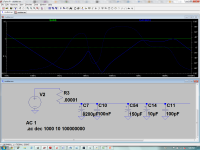
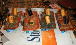
I used LM675T power opamps. The power caps are 8200uF Pany TS bypassed with 100nF MKPs. In the amplifier section I have 35v 150uf Pany FMs, 10uF tantalums, and 100pF NG0 ceramics. I made a "good faith" attempt at modelling the power supply impedance using the method described by Thorsten here. Whether the modeling and subsequent lower supply impedance at high frequencies results in improved sound quality is an open question, but I figure it is better than shooting in the dark. If the power supply and the amp sections were separated RC snubbers (.5R-1R, 330nF) after the power caps would improve performance but with them so close together I opted not to snubberize.
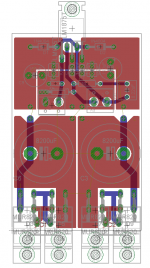
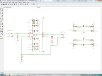
Layout was done in Eagle and I made the PCBs.
Roger
My CCS singled-ended class A MOSFET amp got me searching for an alternative that was equally simple but a little cheaper to build. The cost of large transformers, big caps, and huge heatsinks seems to add up pretty quick. My search led me to current-drive.info where a very simple current feedback method is described. The vetting of Esa's book can be found here. (I bought a copy.)
Rod Elliot describes essentially the same thing in Project 56 but actually explicitly states that the current drive system I'm using "should never be used in practice" for stability and interference concerns.
From Esa's accounting and my prototyping experience I can say that the zobel on the output is mandatory. Without it I had some low frequency instability. The flyback diodes on the output protect the driver when the amp is powered on. As far as interference is concerned, from my experience it is much less susceptible to noise compared to my voltage-driven chipamps.I used LM675T power opamps. The power caps are 8200uF Pany TS bypassed with 100nF MKPs. In the amplifier section I have 35v 150uf Pany FMs, 10uF tantalums, and 100pF NG0 ceramics. I made a "good faith" attempt at modelling the power supply impedance using the method described by Thorsten here. Whether the modeling and subsequent lower supply impedance at high frequencies results in improved sound quality is an open question, but I figure it is better than shooting in the dark. If the power supply and the amp sections were separated RC snubbers (.5R-1R, 330nF) after the power caps would improve performance but with them so close together I opted not to snubberize.
Layout was done in Eagle and I made the PCBs.
Roger
Attachments
-
 IMG_0620 (Custom).JPG109.4 KB · Views: 599
 -
 IMG_0624 (Custom).JPG111.9 KB · Views: 619
 -
 IMG_0628 (Custom).JPG136.1 KB · Views: 803
 -
 IMG_0630 (Custom).JPG106.9 KB · Views: 783
 -
 IMG_0632 (Custom).JPG75.3 KB · Views: 579
 -
 layout.png58.7 KB · Views: 554
 -
 schematic.png104.7 KB · Views: 442
 -
 ps_impedance.png112.3 KB · Views: 479
Last edited:
Junk Parts Gainclone
Here is the junk parts gainclone, set of monoblocks. These are a 500 VA PS and Bridge Parallel LM4780s.
Link to DIY Audio Thread
Sounds better than I thought it would, but the little bricks do get hot.
Here is the junk parts gainclone, set of monoblocks. These are a 500 VA PS and Bridge Parallel LM4780s.
Link to DIY Audio Thread
An externally hosted image should be here but it was not working when we last tested it.
An externally hosted image should be here but it was not working when we last tested it.
An externally hosted image should be here but it was not working when we last tested it.
Sounds better than I thought it would, but the little bricks do get hot.
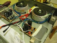
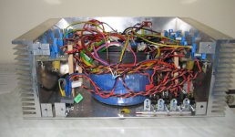
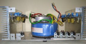
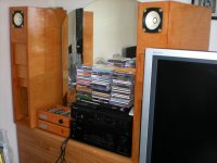
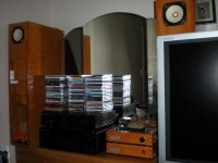
This my 8 channel Gainclone with LM3886 that i' ve use for almost two years now, and i must say i am very happy with the sound.
Power supply uses a transformer 800VA 26+26 V and 94.000μF.
The amp drives drive my 3 way open baffle speakers using active xovers, so only 6 channels are used for the moment.
Power supply uses a transformer 800VA 26+26 V and 94.000μF.
The amp drives drive my 3 way open baffle speakers using active xovers, so only 6 channels are used for the moment.
Attachments
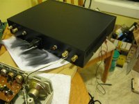
Retro look Gainclone
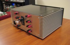
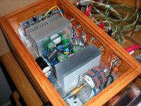
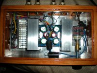
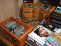
Some more pix... Just brief Description, This is a regulated version gainclone with a supply of around +-28v, I used Peter Daniel's pcb's, with the Zobel network connected and ci used. Its connected to a DIY speaker as well, a backloaded horn using Fostex FE126en. This is my first DIY projects and I'm loving it...The sound? well.. its fantastic!!
Some more pix... Just brief Description, This is a regulated version gainclone with a supply of around +-28v, I used Peter Daniel's pcb's, with the Zobel network connected and ci used. Its connected to a DIY speaker as well, a backloaded horn using Fostex FE126en. This is my first DIY projects and I'm loving it...The sound? well.. its fantastic!!
Attachments
I see many exposed conductive parts.Some more pix... l.. its fantastic!!
How have you connected them to the Safety Earth, when there is no enclosing metal chassis?
My now ~8yr old 6 channel DAC + bridged gainclone amp...
Still works perfectly
My design & home made double sided PCBs.
#1
An externally hosted image should be here but it was not working when we last tested it.
#2
An externally hosted image should be here but it was not working when we last tested it.
#3
An externally hosted image should be here but it was not working when we last tested it.
#4
An externally hosted image should be here but it was not working when we last tested it.
#5
An externally hosted image should be here but it was not working when we last tested it.
Wow! mind to share some more? Do you use one ground plane for the whole system? Grounding such a multichannel PCB can be a challenge and we can all learn from your information, so please share..
With kind regards,
Bas
- Home
- Amplifiers
- Chip Amps
- Chip Amp Photo Gallery