Hi guys.
The bar is an RF wire silver coated.
That's a useless feature, just cosmetic.
I get it at work.
The baby sounds good.
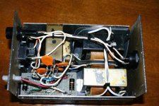
The only concern is that after a while of listening at half power (or more) the heatsinks are getting hot.
The supply voltage is +/- 36V, that's why the power dissipation is high.
The fan "sucks" out the air that enters from the holes under the heatsinks.
The bar is an RF wire silver coated.
That's a useless feature, just cosmetic.
I get it at work.
The baby sounds good.
The only concern is that after a while of listening at half power (or more) the heatsinks are getting hot.
The supply voltage is +/- 36V, that's why the power dissipation is high.
The fan "sucks" out the air that enters from the holes under the heatsinks.
There is no such thing as an approval for a CE mark. Those marks are freely available. By sticking that on manufacturers guarantee that the equipment complys with all relevant norms, laws and regulations in the EU. What makes it even more ridiculous is that all manufacturers are obliged to stick it on their equipment, as soon as they bring it into traffic in the EU.udailey said:So, when did you get approval for your CE mark?")
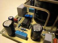
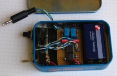
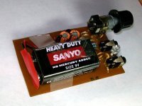
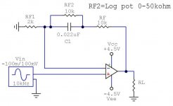
Here is my second attempt on Cmoy amp. It is still a half-prototype but way better looking then my first Cmoy. Input caps are Epcos MKT (blue color) and the red Wimas are for active bass-boost on OPA2132 fedback. The 50k pot is to adjust the amount of bass from 0 to +12dB or so. The second chip is KIA 4558F and is used as voltage splitter to get +-4.5V from 9V battery.
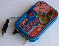
Well, I couldn't find Altoids around here so this tin can is the best thing I could get in a hurry to finish the project.
Well, I couldn't find Altoids around here so this tin can is the best thing I could get in a hurry to finish the project.
Attachments

@ Igla
can you give show bass boost schematic for ur cmoy. i also made a headphone amplifier as a Mini3 clonehttp://kuldeep.biz/2009/06/mini3-inspired-headphone-amplifier.html . i wish to add bass boost in this
can you give show bass boost schematic for ur cmoy. i also made a headphone amplifier as a Mini3 clonehttp://kuldeep.biz/2009/06/mini3-inspired-headphone-amplifier.html . i wish to add bass boost in this
Attachments
DIY Mini3 headphone amplifier clone
its a 3 channel headphone amplifier with precision virtual rail splitter
http://2.bp.blogspot.com/_ff7S7z_e7bI/Sj_mlve2iMI/AAAAAAAADTA/unlaup7GE2Y/s1600-h/100_2777.JPG
http://3.bp.blogspot.com/_ff7S7z_e7bI/Sj_msf28UrI/AAAAAAAADTQ/orT3B1fgNtY/s1600-h/100_2779.JPG
its a 3 channel headphone amplifier with precision virtual rail splitter
http://2.bp.blogspot.com/_ff7S7z_e7bI/Sj_mlve2iMI/AAAAAAAADTA/unlaup7GE2Y/s1600-h/100_2777.JPG
http://3.bp.blogspot.com/_ff7S7z_e7bI/Sj_msf28UrI/AAAAAAAADTQ/orT3B1fgNtY/s1600-h/100_2779.JPG
Attachments
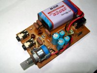
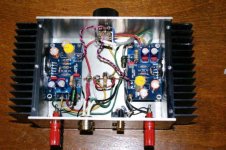
Here is mine (lm3875)
It is very small,but ý'm stisfied
its power stage contains a transformator (150w),two bridge,and four cap (10,000 uf)
PCBs is very small
An externally hosted image should be here but it was not working when we last tested it.
It is very small,but ý'm stisfied
its power stage contains a transformator (150w),two bridge,and four cap (10,000 uf)
PCBs is very small
An externally hosted image should be here but it was not working when we last tested it.
An externally hosted image should be here but it was not working when we last tested it.
- Home
- Amplifiers
- Chip Amps
- Chip Amp Photo Gallery