Igla said:Why are you all so worried about a few mV of DC offset?
21mV DC offset means nothing to you loudspeakers. Even 50 or 100mV offset won't harm your loudspeakers or make them sound worse.
Igla-
For my own information, what would be considered the level to start being concerned with?
I always "assumed" <50mV was acceptable.
All-
This is purely a question to gain personal knowledge NOT to debate or start any "x is better than y" bashing.
It will not harm a woofer or full-range speaker. That might be different, if you use such an amplifier for the tweeter in an active speaker.Igla said:Why are you all so worried about a few mV of DC offset?
21mV DC offset means nothing to you loudspeakers. Even 50 or 100mV offset won't harm your loudspeakers or make them sound worse.
While 100 mV is an accepted offset with chipamps, for solid state amplifiers it would be considered highly unacceptable.
I wonder, if it will not affect the sound. It heats the IC unnecessarily and decreases the headroom. People report that they hear the unmeasurable differences from one capacitor to another. Depending on the rail voltages 100 mV will probably mean something around 1 % less headroom. Plus the headroom reduction that comes from the higher IC temperature. That could have a notable effect.
troystg;
Pass Labs amplifiers states in their users manual (if I recall it right), that DC ofsett is less than 100mV.
I have on all my gainclones (LM1875, LM3875,TDA2050) about 30-50mV offset; I have tried to lower the offset to 0 with capacitor to ground in the feedback loop but the sound was much worse as without capacitor. The same goes for input cap. So I have no input cap and no cap to ground in the feedback loop.
I couldn't find any exact recommendations, how high DC offset is still acceptable. I can just say that your opinion is the same as mine: 50mV or less is acceptable.
pacificbilue;
DC offset for sure decreases the headroom (much more, if you are on the edge) but I can live with that a lot easier then with all those caps - they just mess the sound.
I did try to lower the offset with layout and wirings (without the caps at input and feedback) but I couldn't get lower then 30mV so I can't compare if 30mV sounds worse then 0mV DC offset.
Such a small offset is not a problem for driving speakers. 100mV of offset will result in just over a milliwatt of extra dissipation in an 8 ohm speaker, which is not a problem. (IIRC, the offset of my friend's hybrid amp is 10mV.)pacificblue said:
It will not harm a woofer or full-range speaker. That might be different, if you use such an amplifier for the tweeter in an active speaker.
While 100 mV is an accepted offset with chipamps, for solid state amplifiers it would be considered highly unacceptable.
I wonder, if it will not affect the sound. It heats the IC unnecessarily and decreases the headroom. People report that they hear the unmeasurable differences from one capacitor to another. Depending on the rail voltages 100 mV will probably mean something around 1 % less headroom. Plus the headroom reduction that comes from the higher IC temperature. That could have a notable effect.
For certain test and measurement uses, however, such an offset can skew the results. In that case, add a trimmer to remove the offset. Or better, use a circuit (digital sample and hold based) to rezero the output on command.
didn't want to start a debate...was just wondering whether 21mV offset was fine ? I was never concerned about offset earlier..I have been building STK series and other chipamps for arnd 10 years now, my current amp has 2 *TDA1514A sounds pretty good never bothered measuring it's offset ...only after I read some of the posts here tat I started to think of it..and decided to measure.
Beftus said:An externally hosted image should be here but it was not working when we last tested it.
An externally hosted image should be here but it was not working when we last tested it.
An externally hosted image should be here but it was not working when we last tested it.
Here's my first ever chip amp using the PCBs from BrianGT (chipamp.com). I finished both monoblocks yesterday. They sound great, a wide and detailed soundstage. Much to the dismay of my wife I can hear the difference to my Cambridge Audio 540A amp...
The design is far from original, I've seen more people use these aluminium enclosures, but I really like their look.
Specs:
- 2x Amplimo toroids 2x22V 80VA
- all 0.1 uF caps Vishay-Roederstein MKP1837
- all electrolytics from Panasonic (FC and TS)
- MUR820 rectifier diodes (couldn't find 860's locally)
- all resistors are metal film types
I hooked up the PSU and amp boards using 0.6mm (approx. AWG 23) solid core wire. For the signal output I used 1.4mm (approx. AWG 15) solid core wire.
Measurements taken after completion:
- DC rail voltages left & right channel: 30.3V & 30.8V
- DC offset left & right channel: 1mV & 0.4mV (may not be very accurate, measured with a dirt cheap DMM)
I may improve the aesthetics by replacing the front plate with a piece of wood (oil finished oak from a leftover piece of floorboard). To improve the WAF there's not gonna be a power LED.
WRT the rail voltages, do I need to worry about the little difference? DC offsets appears to be very low, I might check DC offsets again with a real DMM.
Next project will be a matching passive preamp/source selector. At the moment I use the preamp out of the 540A amp.
You should use much thicker wire for the PSU to amp hookup. You are saying that you are using .6mm for that link, yet using much thicker cable for the amp output... the PSU links are supplying that current you are so carefully trying to NOT limit using that thick cable at the output. You need to make the psu links as big, or even thicker, otherwise their resistance will limit your current from the psu to amp, and in the same vein, where is the earth return from the amp modules to the PSU?
The datasheet specifies 10 mV as typical and 100 mV as maximum value for the input DC offset. The feedback cap does not remove it, but only reduces the gain at DC to 1. In other words you get the same DC offset at the outputs as at the input. If you want to get rid of DC offset, you can use a potentiometer/trimmer or a DC servo.Igla said:I did try to lower the offset with layout and wirings (without the caps at input and feedback) but I couldn't get lower then 30mV so I can't compare if 30mV sounds worse then 0mV DC offset.
star882 said:
Such a small offset is not a problem for driving speakers. 100mV of offset will result in just over a milliwatt of extra dissipation in an 8 ohm speaker, which is not a problem.

Yet there are people out there (and out here), who claim to hear the difference between a carbon film and a metal film resistor in the feedback path. Guess what they must make of the destructive influence of 100 mV offset.
pacificblue said:
Yet there are people out there (and out here), who claim to hear the difference between a carbon film and a metal film resistor in the feedback path. Guess what they must make of the destructive influence of 100 mV offset.
its them carbon atoms! little buggers!!
" ... people out there (and out here), who claim to hear the difference between a carbon film and a metal film resistor in the feedback path. ..."
You can see it on a 'scope or distortion analyzer ... but I can no longer to claim an auditory difference ... too old = 64+
" ... 100mV of offset will result in just over a milliwatt of extra dissipation in an 8 ohm speaker, which is not a problem ..."
" ... Guess what they must make of the destructive influence of 100 mV offset. "
= 1/10 Volt ! seems like a lot. Unless that is the voltage required to maintain a transistor in a "turned on" state ... depends on the circuit I suppose.
As long as it is a constant (DC) voltage, the speakers will simple dissipate it as heat, and not much at that ( into 8 Ohms )
From V=IR where R = 8, V = 0.1 then I = 0.0125 Amps ... for power V (Volts) * I (Amps) = P in Watts = 0.00125 = not much, heat or otherwise.
IF, on the other hand, the 100 mV were measurable as a changing sine wave in the audio range, any human could easily hear it, even me.
pacificblue:
Wrong;
Ci capacitor in the feedback loop lowers the output DC offset - when I add Ci cap to the feedback the offset lowers from 30-50mV (depends on the input potentiometer position) to 1-2mV at the output. The sad thing is that Ci cap influence the sound.
So...the sound with Ci caps (Philips, Chemicon, Jamicon or Epcos) in the feedback loop is much worse then without the caps and 30mV DC offset at the output.
Still; never had chance to try the famous BlackGate caps")
About the difference between carbon and metalfilm resistors and if you like - the difference in sound with and without 8 pieces of 5cm brass binding posts...
well, perhaps some other day.
Wrong;
Ci capacitor in the feedback loop lowers the output DC offset - when I add Ci cap to the feedback the offset lowers from 30-50mV (depends on the input potentiometer position) to 1-2mV at the output. The sad thing is that Ci cap influence the sound.
So...the sound with Ci caps (Philips, Chemicon, Jamicon or Epcos) in the feedback loop is much worse then without the caps and 30mV DC offset at the output.
Still; never had chance to try the famous BlackGate caps
About the difference between carbon and metalfilm resistors and if you like - the difference in sound with and without 8 pieces of 5cm brass binding posts...
well, perhaps some other day.
Attachments
" Ci capacitor in the feedback loop lowers the output DC offset ... The sad thing is that Ci cap influence the sound. ..."
ANY cap, BlackGate or other, will do this ...
You might look for a way to better get a handle on where the offset is coming from. On a chip amp, this would be problematic, since you may only have access to the external part of feedback loop and power supply lines.
It may be that the only way you can really control the DC offset is by tweaking the power supply rails ... check to see if the PS rails have a voltage differential ( +/0/- Vcc/Vdd may be slightly different by a very few milliVolts.)
FastEddy;
-I know that any Ci cap (BG or cheap Jamicon) in the feedback loop will lower the DC offset voltage at the output.
-I know that any Ci cap (BG or something else) in the feedback loop will affect the sound.
-I know that cheap caps (Jamicon, Chemicon, Philips and Epcos) in the feedback loop affects the sound in a way that the sound is much better without the caps.
-But I do not know how BG caps affect the sound because I don't have them and I won't have them in the near future because I don't believe in BG price/quality ratio.
-I am not concerned because of a few 10mV of DC offset at the output on my gainclone.
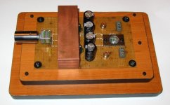
I have tried a few things with wires and layout to lower the output DC offset just to play around. I have also tried a lot of things to tweak the sound but lately I just leave my gainclone as it is - with Jamicon 1000uF PS caps, metalfilm resistors, no input caps and no feedback caps.
-I know that any Ci cap (BG or cheap Jamicon) in the feedback loop will lower the DC offset voltage at the output.
-I know that any Ci cap (BG or something else) in the feedback loop will affect the sound.
-I know that cheap caps (Jamicon, Chemicon, Philips and Epcos) in the feedback loop affects the sound in a way that the sound is much better without the caps.
-But I do not know how BG caps affect the sound because I don't have them and I won't have them in the near future because I don't believe in BG price/quality ratio.
-I am not concerned because of a few 10mV of DC offset at the output on my gainclone.
I have tried a few things with wires and layout to lower the output DC offset just to play around. I have also tried a lot of things to tweak the sound but lately I just leave my gainclone as it is - with Jamicon 1000uF PS caps, metalfilm resistors, no input caps and no feedback caps.
Attachments
" ... I am not concerned because of a few 10mV of DC offset at the output on my gainclone. ..."
OK ... As long as you are experimenting, you might still try to tweak the voltage differential between the PS rails and to the ground (reference). It is true that 10 mVolts is not a whole lot, especially if it is pure DC, merely dissipating as heat through the speakers ...
Your photos give a nice new twist on "bread boarding" ... Keeps the faith in chip amps.
pacificblue said:The feedback cap does not remove it, but only reduces the gain at DC to 1. In other words you get the same DC offset at the outputs as at the input.
Igla said:Ci capacitor in the feedback loop lowers the output DC offset - when I add Ci cap to the feedback the offset lowers from 30-50mV (depends on the input potentiometer position) to 1-2mV at the output.
Isn't that the same? Let me guess.. your AC gain is around 30?
Might as well throw the whole circuit in liquid nitrogen...pacificblue said:Yet there are people out there (and out here), who claim to hear the difference between a carbon film and a metal film resistor in the feedback path. Guess what they must make of the destructive influence of 100 mV offset.
I know mybe is off topic, but..
Hello, I must say that all of you have done a wonderful job with your gainclones here. Very nice pictures!
And very inspiring as well
Also, I was reading about DC offset at the input speakers (or gainclone output). My thinking is that not only produces heat, where 100mV is not to be worried about, but also moves the speaker's cone (up or down).
Moving away from perfect equilibrium, where we'll have the maximum symmetry. I mean (and I'm sorry i'm not familiar with the term in english): a direct translation would be "symmetric maximum excursion"
This excursion is the one for the speaker cone, example peak to peak 12mm, so it can goes 6mm top and 6mm bottom.
any DC applied to the speakers (on this example) will move up some XXmm, so the new excursion for this speaker will be:
6mm - XXmm --> it won't be the maximum, it's asymmetric now.
Also (because of this offset) it might cut audio signals causing distortion, therefore an increase of resulting DC (seeing on Fourier series), and there could we have worse heat problems and kill the speakers (as I did some years ago).
Anyway I'm so sorry about terminology and my bad english, it's because i'm not familiar with (both), but I will get used to it, i promise.
All of this is In My Humble Opinion, and if I mistaken please, help me improve my (very little) knowledge.
Keep sending some nice pictures, keep on the hard work you've been doing, and I hope to build a GC soon.
Regards.
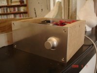
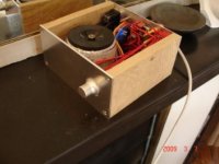
I've just finished my LM1875 chipamp kit,
it works fine. The heatsink is provided by rear aluminium plate,
it seems to be enough for 8 ohms speakers. I can't tell too much about how it sounds because I've connected it with a pair of old speakers that I picked up from my garage - my hemp acoustics FR8C's box are not ready yet. A few year ago those old speakers where used with a nad C300 integrated amp ; I find my new LM1875 chipamp finer than the nad, with more transparency. Volume control is provided by an alps 50kohms potentiometer. The amp is not absolutely quiet, there is something like a little hum that comes from the transformer, but I can't ear it in my listening position...
Attachments
- Home
- Amplifiers
- Chip Amps
- Chip Amp Photo Gallery