Here's mine (4)
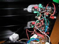
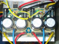
The chips are mounted to the top surface of the box. The IO wiring wasn't too bad, but things were definitely getting tight by the time I finished.
I found that implementing a complete circuit with input, feedback and output filters, plus mute switches really taxes the contraption (orderly structure?) you wind up constructing. Mick Feuerbacher’s minimalist chip amps look a lot better.
Attachments
Here's mine (5)
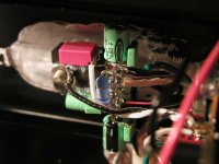
I was surprised by the results, good sound/no noise. In such a cramped space, I was expecting noise.
The input signal grounds are connected to the ground buss bar on each chip by a single strand from an 18 ga multi-strand wire. This separates the low level signal ground from the output/power ground by about a 0.01 Ù resistance.
A braided cable from the power supply to each chip consists of 18 ga V+, 18 ga V-, and 16 ga 0V wires.
The inputs go from the jacks to the pots, then the ground and wiper lines (black & white wires) go to the chip.
By the way, the box has 1/2" wide ribs on the top and bottom surfaces. I had to cut the ribs out of the way to mount the chips. Did you know you can machine aluminum with an end-cutting router bit and a small drill press? You can't do it well, but you can do it...")
I was surprised by the results, good sound/no noise. In such a cramped space, I was expecting noise.
The input signal grounds are connected to the ground buss bar on each chip by a single strand from an 18 ga multi-strand wire. This separates the low level signal ground from the output/power ground by about a 0.01 Ù resistance.
A braided cable from the power supply to each chip consists of 18 ga V+, 18 ga V-, and 16 ga 0V wires.
The inputs go from the jacks to the pots, then the ground and wiper lines (black & white wires) go to the chip.
By the way, the box has 1/2" wide ribs on the top and bottom surfaces. I had to cut the ribs out of the way to mount the chips. Did you know you can machine aluminum with an end-cutting router bit and a small drill press? You can't do it well, but you can do it...
Attachments
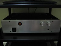
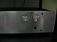
Replace switch!
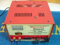
Hello, I just replaced the toggle switch for a DP Rocker switch.
as you can see now the light is where the toggle switch was and the DP Rocker switch is where the light was (you can not see it well because the switch is black in rectangular hole). I think it looks nicer.and also I made small "holes" on top of the volume control to mark the volume and bigger ones for the input.
Attachments
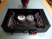
Here is my first try at a gainclone. I used BrianGT's PS and amp boards and sourced my own components. The chassis was from a fried Haffler amp.
My first pass and I had no hum or other unwanted noise. DC offset is 0.1 mv in both channels. Sound is excellent and there is very little noise when sitting idle and gain is turned up on the preamp. I still have a little work to do with the cosmetics.
My first pass and I had no hum or other unwanted noise. DC offset is 0.1 mv in both channels. Sound is excellent and there is very little noise when sitting idle and gain is turned up on the preamp. I still have a little work to do with the cosmetics.
Attachments

Not mine (a friend's) but it is the most impressive one I have seen. It is a hybrid digital and it is so efficient that it only uses one watt at normal listening levels! It was recently presented at a university engineering show.
http://ecorenovator.org/forum/appliances-gadgets/358-amanda-harris-prius-home-audio.html
Schematic:
http://i41.tinypic.com/2r4pwlh.png
Insides:
http://i42.tinypic.com/29fpk5e.jpg
My friend calls it "the Prius of home audio". Particularly interesting is the configuration of the output filter that he claims lets the chipset use 3 level modulation and therefore improve efficiency. Based on his design, I have an idea to build one that uses half the power but has only half the output power rating. Use only one chipset, with one input accepting a noninverted input and the other an inverted input. At the output, connect two speakers in series with the midpoint connected through an inductor and capacitor to ground. The low frequencies (which don't have much stereo effect) don't go through the capacitor at all, but higher frequencies go through the filter allowing for stereo differences. (Maybe I should call my idea "the Insight of home audio"?)
http://ecorenovator.org/forum/appliances-gadgets/358-amanda-harris-prius-home-audio.html
An externally hosted image should be here but it was not working when we last tested it.
Schematic:
http://i41.tinypic.com/2r4pwlh.png
Insides:
http://i42.tinypic.com/29fpk5e.jpg
My friend calls it "the Prius of home audio". Particularly interesting is the configuration of the output filter that he claims lets the chipset use 3 level modulation and therefore improve efficiency. Based on his design, I have an idea to build one that uses half the power but has only half the output power rating. Use only one chipset, with one input accepting a noninverted input and the other an inverted input. At the output, connect two speakers in series with the midpoint connected through an inductor and capacitor to ground. The low frequencies (which don't have much stereo effect) don't go through the capacitor at all, but higher frequencies go through the filter allowing for stereo differences. (Maybe I should call my idea "the Insight of home audio"?)
Re: Here's mine
lhwidget where did you get that case?????? I'm actually about to die of wanting some of those right now.lhwidget said:I wanted to build a rugged, small, 30 to 50 watt amp for testing speakers and casual use. Beftus (post 860) and Matjans (post 32) povided the ideas. The schematic is Rod Elliott's
http://sound.westhost.com/project19.htm
and Mick Feuerbacher’s methodology & layout was used to build the circuits http://www.dogbreath.de/Chipamps/GainCardCopy/GainCardCopy.html
This is a dual channel amp, completely contained in one case about 3" tall, 5 3/4" wide, and 8" long.
I consider myself unbelievably lucky, this amp makes zero noise. No hum, no thumps, ticks, or hiss. I have no sophisticated test gear, just an old used scope and a cheap signal generator, however, the amp's output changes less that a trace's thickness from 20 Hz to about 100 kHz. I'm really pleased with it
Re: Re: Here's mine
Don't forget the ridges inside (see pic above). If those aren't a problem, it's a great case.
http://cgi.ebay.com/Aluminum-Projec...main_0?hash=item250323035406#ebayphotohosting
raypalmer said:lhwidget where did you get that case?????? I'm actually about to die of wanting some of those right now.
Don't forget the ridges inside (see pic above). If those aren't a problem, it's a great case.
http://cgi.ebay.com/Aluminum-Projec...main_0?hash=item250323035406#ebayphotohosting
sasmit said:a paralell design....blue ones panasonic audio grade caps , two FC 1000ufs , wima 2.5 mm polypropylene, tyco 0.1% resistors.
work in progress...
I'm getting around 21mV DC offset ...is this okay ?
- Home
- Amplifiers
- Chip Amps
- Chip Amp Photo Gallery