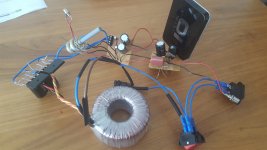
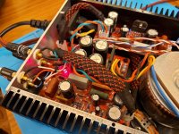
Spent 2020 lockdown doing a prototype version of an LM3886 amp. Bit of a progress between the first photo and the latest.
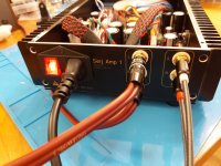
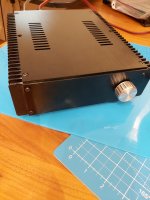
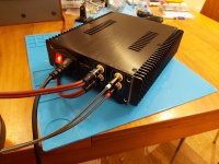
And now use this amp every day (still need to get better front-panel for it).
And now use this amp every day (still need to get better front-panel for it).
Attachments
-
 20200611_120332.jpg323.3 KB · Views: 573
 -
 20210804_012623.jpg446.1 KB · Views: 554
 -
 20210804_012634.jpg427.8 KB · Views: 572
 -
 20210901_165832.jpg524.6 KB · Views: 584
 -
 20210910_022311.jpg465.3 KB · Views: 596
 -
 20210910_022335.jpg399.2 KB · Views: 566
 -
 20210910_023111.jpg418.9 KB · Views: 523
 -
 20210910_023124.jpg430.9 KB · Views: 552
Member
Joined 2009
Paid Member
maybe add a valve on the top for the real deal? Perhaps a simple cathode follower buffer at input.Nice. That transformer on the top gives it a bit of "valve look".
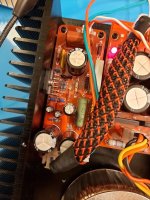
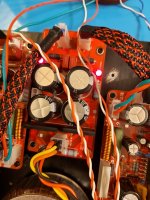
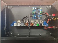
My current project: Plate amplifier for my living room sub. It will be able to run in a 2.1 configuration. The TDA7293s on the board are in a 2xParallel configuration, allowing me to have speakers with low impedance as my tops. The Amp for the woofer will be a IRS2092 based module, that is not part of this PCB.
On top, I've added DC protection using a µPC1237 and a ADAU1701 as a DSP. For input either unbalanced or balanced analogue audio is supported. If required, I can use TOSLINK or S/PDIF as input as well, translated via a WM8804 that transforms it into I²S.
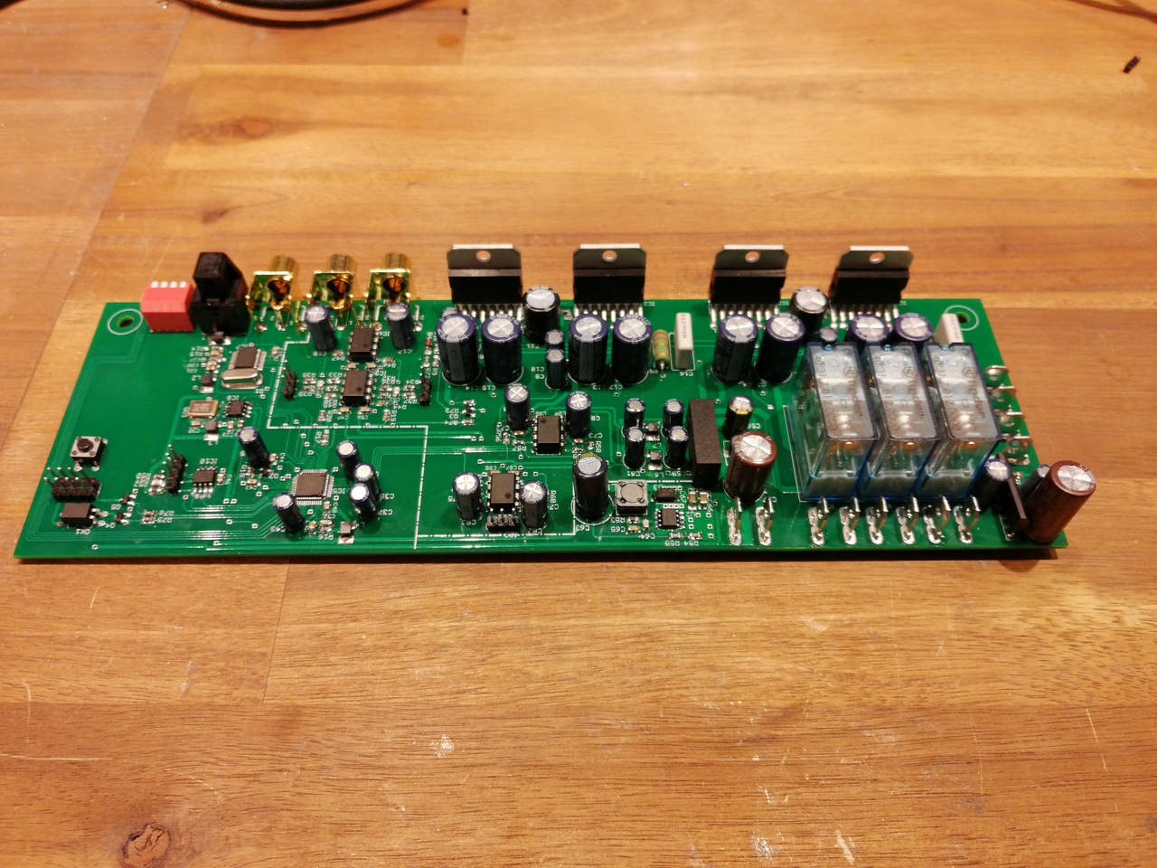
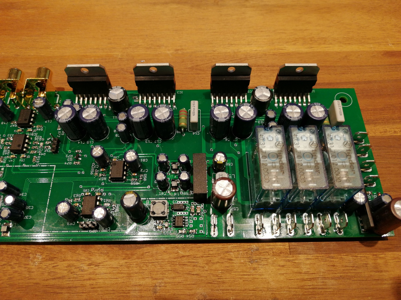
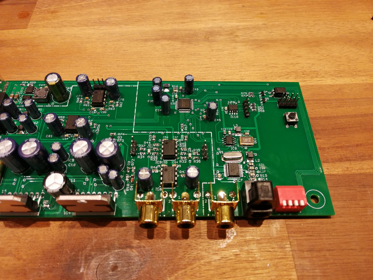
On top, I've added DC protection using a µPC1237 and a ADAU1701 as a DSP. For input either unbalanced or balanced analogue audio is supported. If required, I can use TOSLINK or S/PDIF as input as well, translated via a WM8804 that transforms it into I²S.


G'day Guys,
May I present a project I've been brewing for a while.
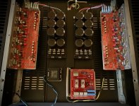
A dual mono gainclone using 00940's LM3886 boards.
The rest is all home brew: chassis, cap banks, rectifier boards, speaker protection boards etc.


It's been quite the experiment. Many things I will do differently on the next power amp but this one was designed as a backup amp so mistakes and learnings are ok!
May I present a project I've been brewing for a while.
A dual mono gainclone using 00940's LM3886 boards.
The rest is all home brew: chassis, cap banks, rectifier boards, speaker protection boards etc.
It's been quite the experiment. Many things I will do differently on the next power amp but this one was designed as a backup amp so mistakes and learnings are ok!
Love the tight twisting of pairs and the separation of power from signal!G'day Guys,
May I present a project I've been brewing for a while.
A dual mono gainclone using 00940's LM3886 boards.
The rest is all home brew: chassis, cap banks, rectifier boards, speaker protection boards etc.
View attachment 1058747
View attachment 1058748
It's been quite the experiment. Many things I will do differently on the next power amp but this one was designed as a backup amp so mistakes and learnings are ok!
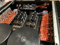
Bottom row: LM3886 Gainclone PCBs. Not minimalist, but minimal. Specifications agree or better than those stated by IC manufacturer.
Top row: 5A fused AC-DC power supplies with individual rectifier diode snubbing. Transformer used, 22-0-22V AC nominal all large capacitors 50V but to be fair, 35V will have been quite adequate.

Top row: 5A fused AC-DC power supplies with individual rectifier diode snubbing. Transformer used, 22-0-22V AC nominal all large capacitors 50V but to be fair, 35V will have been quite adequate.
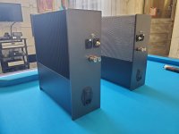
Here are my vertically oriented & mirrored Modulus 686 monoblocks. These have been 'nearly finished' for years. I just finished DIY powder coating the panels.
Attachments
"Top row: 5A fused AC-DC power supplies with individual rectifier diode snubbing. Transformer used, 22-0-22V AC nominal all large capacitors 50V but to be fair, 35V will have been quite adequate."
If I understand correctly- you are using single transformer, but multiple bridge rectifiers+filters? So each chipamp module has its own rectifiers + filters set. Can you please elaborate advantages/ disadvantages of such setups
Yes nice, the perfect R-core transformer. Where do you get them from, because I can't find any R-core transformers with 300VA. And I already googled Selectronic.
heatsink enclosure for 3886 RefC
It looks great, beautiful!!!!
Hello,
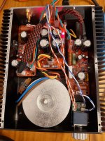
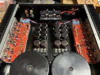
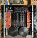
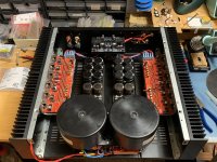
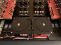
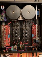
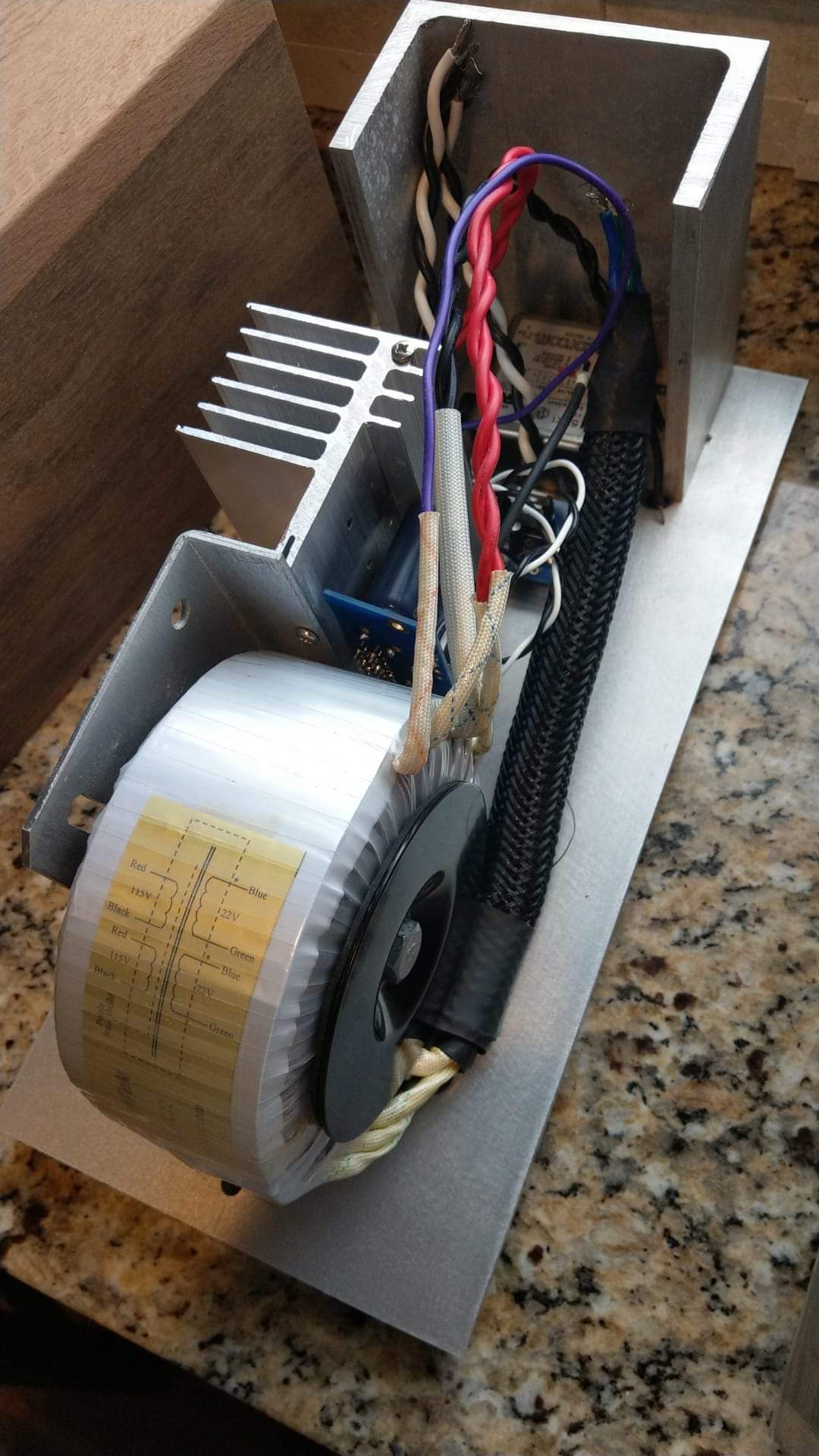
I built this power amplifier 6 years ago and started to completely rework it during the Corona period. That's the current status. I still have to adapt the secondary lines (I don't like wires, I prefer stranded cables) so that the transformers finally find their place. I still need to solder the signal wires and continue assembling the case. Unfortunately, by the front panel is left for the time being, because I don't want to take over the old one and I don't have a new one yet.
I built this power amplifier 6 years ago and started to completely rework it during the Corona period. That's the current status. I still have to adapt the secondary lines (I don't like wires, I prefer stranded cables) so that the transformers finally find their place. I still need to solder the signal wires and continue assembling the case. Unfortunately, by the front panel is left for the time being, because I don't want to take over the old one and I don't have a new one yet.
Attachments
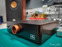
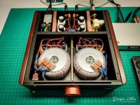
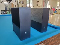
Finally! it was a very long journey with my audiosector kit from 10+ yrs ago. I found the hardest part was a home(case) for the amp and PSU. In the end mono blocks with a simple passive matching theamed pre amp. I carried the indicator LED via fiber optic to a small hole 1/16" on the base plate. I didn't want to take away from the beauty of the wood") I have been driving a vintage set of B&W 500 series floor standers, the listening experience is most pleasurable.
I have been driving a vintage set of B&W 500 series floor standers, the listening experience is most pleasurable.


I have been driving a vintage set of B&W 500 series floor standers, the listening experience is most pleasurable.
Last edited by a moderator:
the back of the amp is not sealed, I guess it could also release from the bottom plate. theres quite abit of aluminum and its all conected together with thermal paste.Absolutely stunning, and that is incredible wood!
How does the heat get out?
Used the Audiovector brds myself. Use my chip amp in system #3 around the TV with a SS preamp driving Markaudio speakers. Built mine in a 1U enclosure with two low profile trannies. Love your timber enclosure.
http://retro-thermionic.blogspot.com/2019/07/overture-lm4780-chip-power-amp.html
http://retro-thermionic.blogspot.com/2019/07/overture-lm4780-chip-power-amp.html
- Home
- Amplifiers
- Chip Amps
- Chip Amp Photo Gallery