I resized them locally and am prepared to upload them to my personal hosting and re-link but there's no "edit" button showing up on my post (I assume it would be next to "quote"?), and looking through "attachments" on my control panel allows me to review attachments but not to replace or delete them, so it appears we're stuck with them.Please remember to resize your photos before posting. No need for 1 MB images on the web. Thanks.
http://www.diyaudio.com/forums/everything-else/183084-pictures-why-not-attach-them.html
In the future I'll be more considerate of those browsing via home built tube-based dialup modems.
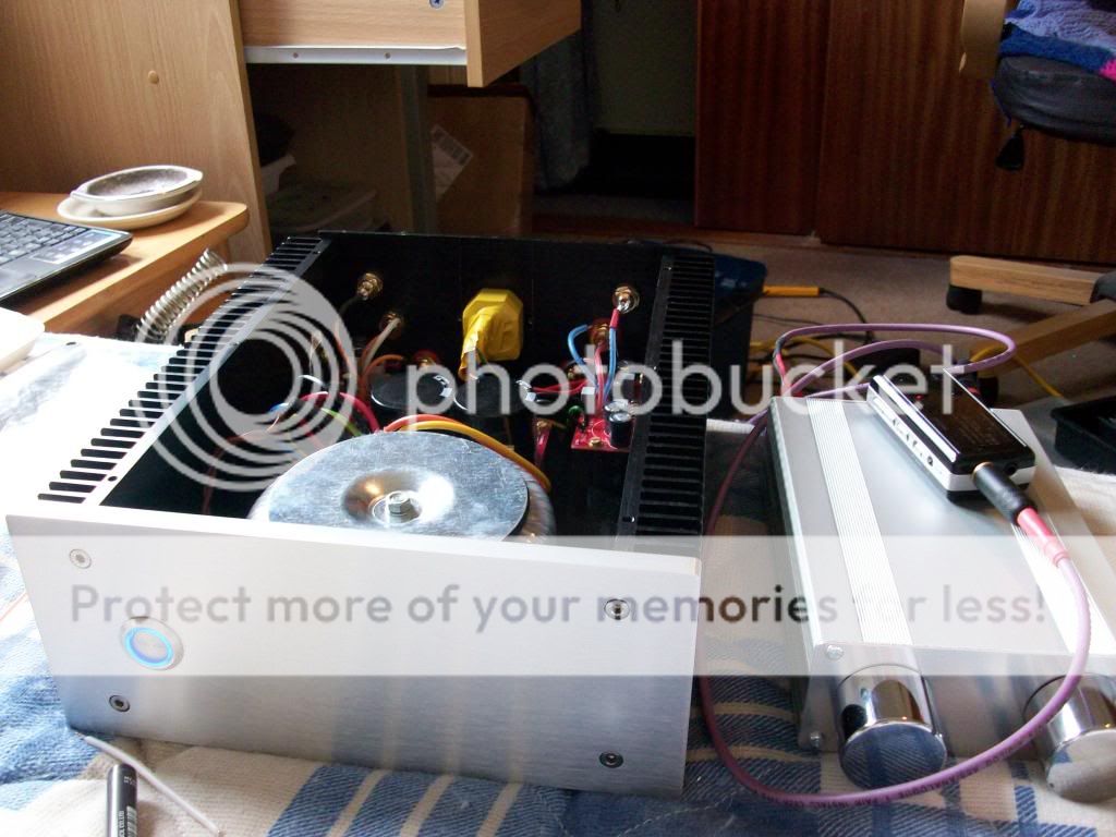
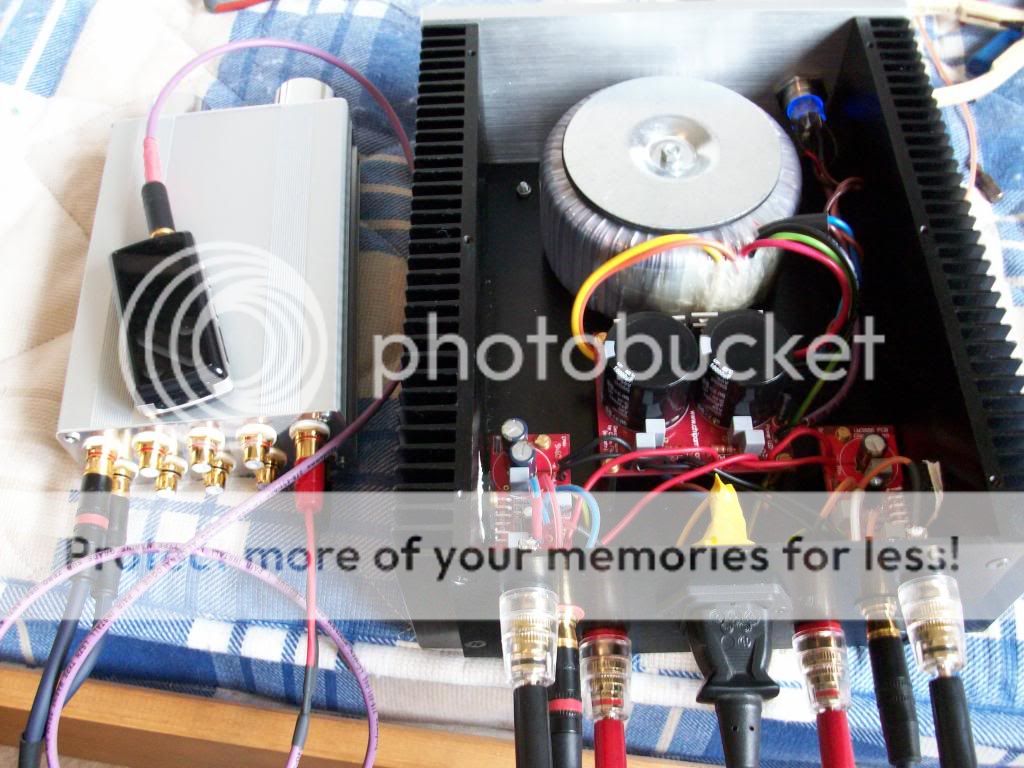
WoW! I clicked on the second pic and a toroidal the size of an lp appeared 
I agree that is too good an amp for an industrial work place.
I built a little 10 watt per channel Quasar 3088 amp kit based around aTDA2009A chip some time back, very cheap and surprisingly loud and it will run off a pair of 12v lead acid alarm battery's wired in series to give 24v, it will also run off 12v but with much reduced output. Or you can run it off a 24 volt (DC) laptop power supply.
You could stick one in your box along with a couple of old loudspeaker drivers, throw in a battery, plug in an mp3 player and it's a semi portable boom box
I'll look into that. I picked up a couple 24V DC power supplies to test my PCBs before going whole-hog with the assembly, so a TDA2009A might be just the ticket. The current enclosure is trash (MDF, not very reusable and /awful/ when it comes to moisture), but I've been kicking around ideas for a box of similar size that incorporates drivers too, probably made of 1/2" plywood either painted or varnished. 10 watts would be plenty for a shop/party boombox, since too much volume turns the neighbors into a problem.WoW! I clicked on the second pic and a toroidal the size of an lp appeared
I agree that is too good an amp for an industrial work place.
I built a little 10 watt per channel Quasar 3088 amp kit based around aTDA2009A chip some time back, very cheap and surprisingly loud and it will run off a pair of 12v lead acid alarm battery's wired in series to give 24v, it will also run off 12v but with much reduced output. Or you can run it off a 24 volt (DC) laptop power supply.
You could stick one in your box along with a couple of old loudspeaker drivers, throw in a battery, plug in an mp3 player and it's a semi portable boom box
mrWagner: as for the PSU caps, so far I haven't run into any problems with the 1500ufs. What's the failure mode when the caps run out? Total chip shutdown, diminished audio quality, drop in volume? When I was testing the channels with underpowered surplus PSUs the chips would kind of reset themselves and halt output after the caps on the amp boards ran out and until the power switch was cycled (lather/rinse/etc), but I've listened to the completed amp quite a lot with no issue. It's a 250VA transformer, which may or may not make a difference, but it has never given me any indication of being under-juiced.
1500uF causes 6.6V ripple in the supply voltage if you are running on 8W with 8ohm speakers. It is already loud, so maybe you are running on lot lower, causing also lower ripple and the chip can handle it well. But if you push the amp hard, the ripple will go up to 10V. And that is really funky way to power a chip
10 watts would be plenty for a shop/party boombox, since too much volume turns the neighbors into a problem.
Sounds like a good plan, remember that little TDA2009A chip puts out 2 x 10 watts into 8 ohms when running off a 24v dc supply. I could not believe how loud it goes into an old set of 6 ohm Quad 12l stand mount speakers in a smallish room. It is deafening even with the volume quite low on the portable I had playing flac music files through it.
A very simple little amp with surprisingly decent sound quality for about the same price as a new vinyl lp.
 Success! I got my chipamp LM3886 working, again!
Sounds dam good too along with the little passive preamp I made yesterday.
Readings when on are - Right in = -2.9mv Right out = 0.8mv
Left in = -2.9mv Right out = 0.8mv
However with old cheap test speakers connected but no input I get -
Right out = 2.9mv
Left out = 1.2mv
Probably the test speakers i'm thinking
Anyway i'll try posting some pictures but i'm not that good at it yet, still catching up
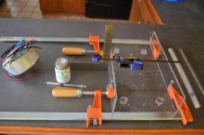
Testing stage.
In my main system tonight making nice sounds through my Rega R3's


In my main system tonight making nice sounds through my Rega R3's
An externally hosted image should be here but it was not working when we last tested it.
Very Nice ! That is the same set (I did monoblocks) I built as my first re-entry into amp building and I still have them. Sounded so good I've been hooked for the last three years. You might do a little more wire twisting as my builds are quite sensitive to external interference (Halogen lights and computer monitors) without it. Your chassis may be providing better isolation.
Know you will enjoy that amp for years.
You might do a little more wire twisting as my builds are quite sensitive to external interference (Halogen lights and computer monitors) without it. Your chassis may be providing better isolation.Know you will enjoy that amp for years.
Thanks Bob. The only thing so far is the predictable mobile phone breakthrough but i'll put up with that. I've been stuck with a fill in amp for too long, a musical fidelity X80 integrated I got cheap (dam recession) anyway it produced plenty of detail but didn't get your foot tapping, if you know what I mean.
This kit however is a very decent amp in my opinion.
I'm trying out that new Tocos pot, see if it's worth the hype type thing. So far i'm quite impressed, runs a Noble pretty close for much less money. I'm also waiting on a couple of miniature stepped attenuators coming from China along with a JC-2 preamp kit, a Jims Audio clone (John Curl's work fascinates me but i'll never afford the real deal) The bits are to make up a gain stage with by-passable passive tone controls. If the attenuators are any good I might get a 20k one for the passive pre I made.
Silante my friend
Davy
The change in output offset is due to the change in input conditions..............Readings when on are - Right in = -2.9mv Right out = 0.8mv
Left in = -2.9mv Right out = 0.8mv
However with old cheap test speakers connected but no input I get -
Right out = 2.9mv
Left out = 1.2mv
Probably the test speakers i'm thinking .................
A shorted input effectively inserts a Source Resistance of zero ohms into the input.
An open input inserts an effective infinite resistance into the input.
Your actual Source will have it's own output impedance. This becomes the Source Resistance seen by the amplifier.
You should check output offset with shorted input and with the Source/s connected and with the Source/s switched on and switched off.
Last edited:
I have that same JC-2 kit and love it. I've never seriously considered another pre since it was built. To my ears it sweetens the sound a bit without adding a lot of coloration. John called it a "straight wire with gain" and it does perform as such. In several other builds I use simple pot attenuation, but where gain is required the Jim's Audio kit excels.
Another item you might want to check out is Uriah Dailey's Resistor Replacer. You can read a review at that thread.
EDIT: RE post 2512 - Take a look at Xnview also. It's been my favorite for several years.
****
Another item you might want to check out is Uriah Dailey's Resistor Replacer. You can read a review at that thread.
EDIT: RE post 2512 - Take a look at Xnview also. It's been my favorite for several years.
****
Attachments
Last edited:
Cheers Andrew, will do mate.
And Cheers to you too Bob, funny that we should pick the same pre and power amp kit's. I was directed to that JC-2 kit by a guy on pink fish media's diy section because I had found the one by tubeshunter, it looked quite good so i was asking for opinions about it when someone linked to Jims Audio's version, better spec components etc swayed me.
After I had ordered it however, I did a search on here and came across a thread on the tubes hunter one which later also covered the one I had ordered. Whaleman seemed impressed with the Jims Audio version which was encouraging.
Out of interest, how hot does this version run? i'm wondering if I can fit one inside the same small enclosure I used for my pot in a box preamp, with the transformer in another similar enclosure. I was going to wait and see how hot it got when on for a while but your impression would be nice.
Davy
You can get some info and examples HERE.
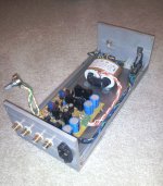
The pics are of the not yet completed (need pot shaft & cover) separate unit build I'm using now. The R-Core transformer bumps up the quality a significant amount - not drastic but well worth the cost..
The pics are of the not yet completed (need pot shaft & cover) separate unit build I'm using now. The R-Core transformer bumps up the quality a significant amount - not drastic but well worth the cost..
Attachments
Looks good Bob! where did you get your enclosure?
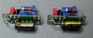
The resistor replacer is interesting too, I was going to try Riken's in that position at some point but before I try any mods I need to get some of those speaker posts which have grub screws instead of trying to solder and desolder to those large bolts with a 25w soldering bolt.
That pot looks like the ones I ordered from ebay, the sellers called gigawork in HK. How do you find them?
Edit, ah I see your a fine craftsman when it comes to enclosures too, nice work!
Last edited:
I checked the readings again today as Andrew T suggested.
They started out higher but slowly dropped to.
Left Out = 01.2
Right Out = 02.9
This with a source connected but turned right down, when I raised the volume to roughly 2/3 the readings fluctuated constantly but did not appear to exceed 0.18
Shorting the inputs gave the same readings as I got with source connected but turned right down.
The amp sounds better than I had hoped for or expected, I guess it's ok now.
I'd like to thank the good folks here who helped me out and gave me some very good pointers.
Cheers
Davy
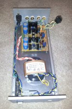
Here's my latest, the Mylo amp (named after my my baby)......
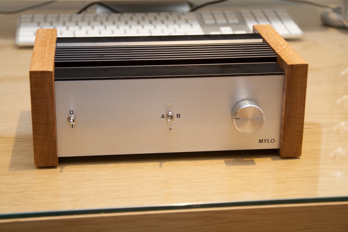
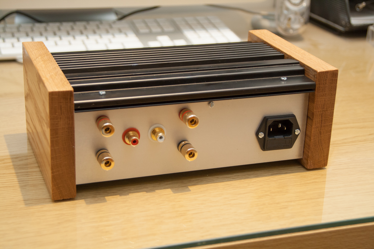
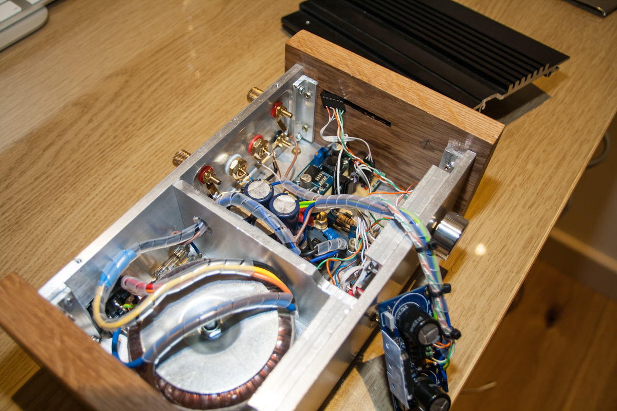
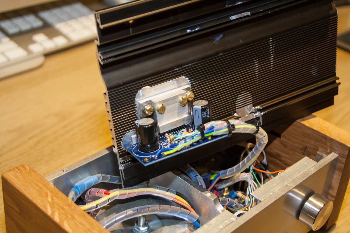
This amp uses an LM4780 chip mounted on one of Peter Daniel's boards. Powered with a 120VA 2 x 0-15V toroid.
The A-B switch on the front allows you to select analogue input (A) or Bluetooth input (B). The Bluetooth module I'm using isn't pictured as I blew up my current one, but it attaches to the 6 way dupont connector which can be seen in picture 3 and slots into the oak side to allow it to receive the Bluetooth signal. The heatsink was acquired from an old variable speed drive.
Again, the sound quality from this amp paired with my full range speakers is as good as expected. The LM4780 chip never fails to impress
another paralleled LM3886 build
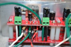
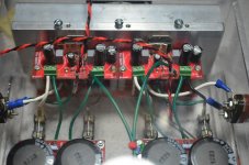
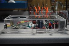
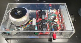
This is a two channel amplifier made from paralleled LM3886's. I used one Chipamp.com board from Brain GT for each chip, then put the boards in parallel. This matches very closely schematic 6.2.1 (PA100-100W parallel circuit) in National's Application Report AN1192. I omitted Cin and Rin is off the board. Rout has one end connected to each board, which can be seen in the close-up photo of the boards. Rails are +/- 34V for, 116 Watts into a 4R load.
The chassis is not the prettiest thing ever. It's my first time working with acryllic. The big hole in the top was from when I had a larger transformer, and will probably be replaced.
Attachments
Latest Gainclone - VU meters
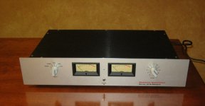
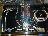
This is my latest gainclone amp. This was built with Peter Daniels PCBs and his minimalist design (DC coupled). It uses all Blackgate caps on the amp and power supply boards, Alps Black beauty volume, Vampire gold/teflon RCAs, Superior BP30 output binding posts, 200VA shielded Antek transformer, and all audio wire is shielded teflon litz. Also has solid copper heatsink. I designed a meter PCB for the Weston meters (same ones used on early Levinson gear), and also used that same PCB for a subwoofer output buffer. LED illumination for the meters, with photographic gel filters to look more like incandescent light. I eventually plan to add a JC-2 circuit as input stage. Faceplate is FrontPanel Express, aluminum chassis is from Ango. Knobs are custom made to match early Levinson gear as well.
Mike
Attachments
- Home
- Amplifiers
- Chip Amps
- Chip Amp Photo Gallery