What if you use 4 or 5 or more 2200uF? that's better than one huge 10.000uF and works well for low range, I think.
paralleling them lowers the ESR (total).
(that's a good thing)
")
Zimmer,
each mains transformer deserves it's own mains fuse.
Each 400VA running on 110/120Vac will likely need a T8A, or T10A to start repeatedly over a large number of years and avoid nuisance blowing.
Fit a soft start to each toroid. The same timer can pull in a double pole single throw relay. One set of poles shorting the resistor in the primary feed to one transformer.
AND put back in the mains fuse that you shorted out !!!They continue to blow, when i switch the amp on. I guess the two 400va toroids use a lot of current initially. Even 6A fuses blow. I currently jumped the fuses......
Last edited:
Zimmer,
each mains transformer deserves it's own mains fuse.
Each 400VA running on 110/120Vac will likely need a T8A, or T10A to start repeatedly over a large number of years and avoid nuisance blowing.
Fit a soft start to each toroid. The same timer can pull in a double pole single throw relay. One set of poles shorting the resistor in the primary feed to one transformer.
AND put back in the mains fuse that you shorted out !!!
Hi Andrew,
Thank you for your reply. We run 230V here. I will install a soft start ASAP and put back the fuses....
Michael
400VA/220Vac = 1.8A. You are probably on a 220Vac mains supply. But it varies a lot.
Use a T1.6A pr T2A for each 400VA with a soft start.
Without a soft start, probably T5A or T6.3A for each.
And the mains fuse to start both, without a soft start, would be around T8A to T12A.
Use a T1.6A pr T2A for each 400VA with a soft start.
Without a soft start, probably T5A or T6.3A for each.
And the mains fuse to start both, without a soft start, would be around T8A to T12A.
Have to agree! there a few members that like to blow there own trumpet!I am Sorry, photo Gallery but it most discussions.
Regard,
Yassud
Lets stick to piccies and forget about trying to get more technical than the last post,
LM4780 Dual Parallel
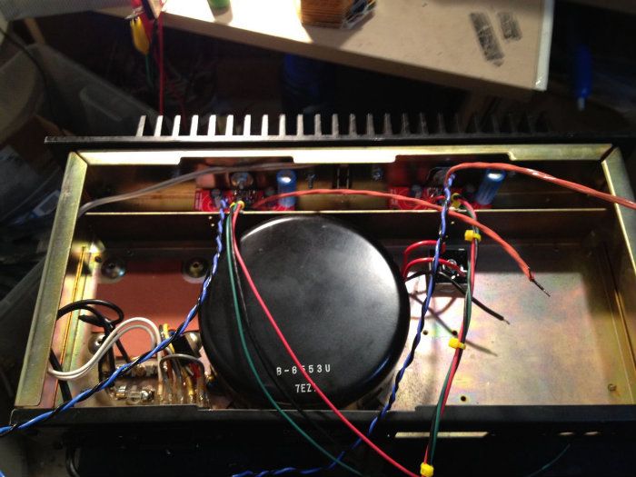
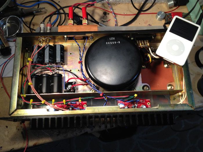
Here is my newly finished AudioSector LM4780 Dual Parallel kit.
I have used the "Snubberized" power supply with 17.2kµF per rail.
The entire chassis was made from parts in my "scrap" bin.
It sounds very nice, even better than when the left channel was running stereo by itself.
Here is my newly finished AudioSector LM4780 Dual Parallel kit.
I have used the "Snubberized" power supply with 17.2kµF per rail.
The entire chassis was made from parts in my "scrap" bin.
It sounds very nice, even better than when the left channel was running stereo by itself.
Attachments
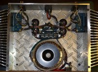
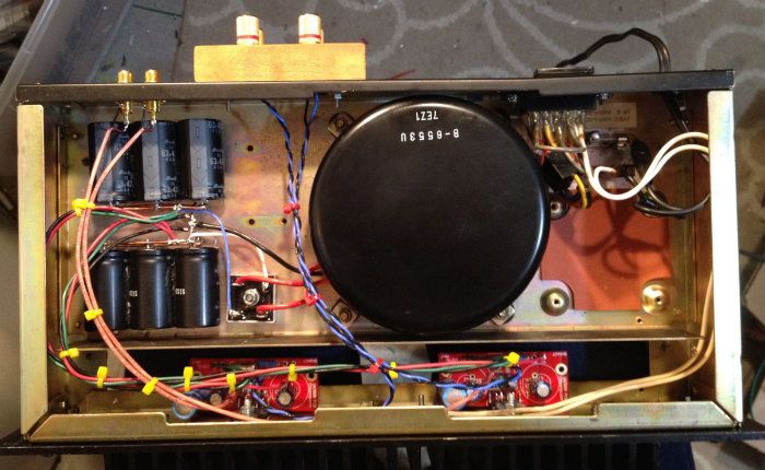
The wood is Hickory flooring with 2 coats of Birchwood Casey Grain Filler and 2 coats of Birchwood Casey Gunstock Wax.
The top is clear plexi, I installed a 10mcd Red LED on the bottom of the PS with 2kΩ resistor on top, you can see the 4 stack of 8.2kΩ resistors in the middle of the PS.
The LED reflects off of the diamond plate concealed by the Toroid for just enough glow to indicate it's on.
The top is clear plexi, I installed a 10mcd Red LED on the bottom of the PS with 2kΩ resistor on top, you can see the 4 stack of 8.2kΩ resistors in the middle of the PS.
The LED reflects off of the diamond plate concealed by the Toroid for just enough glow to indicate it's on.
Attachments
Thank You All BTW for the kind words.
I put about 8 hours into this last Saturday to finish it up.
I had the worst headache I have EVER had (worse than a hangover) with blurry vision and everything after being hunched over the kitchen table that long.
The nice thing about the finish I chose is that I went from plain wood to semi-gloss in 2 hours.
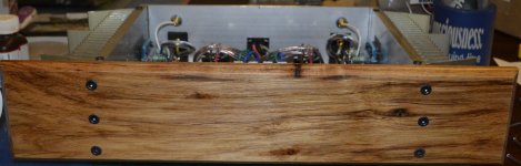
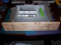
Here is a shot of the wood before the finish.
I put about 8 hours into this last Saturday to finish it up.
I had the worst headache I have EVER had (worse than a hangover) with blurry vision and everything after being hunched over the kitchen table that long.
The nice thing about the finish I chose is that I went from plain wood to semi-gloss in 2 hours.
Here is a shot of the wood before the finish.
Attachments
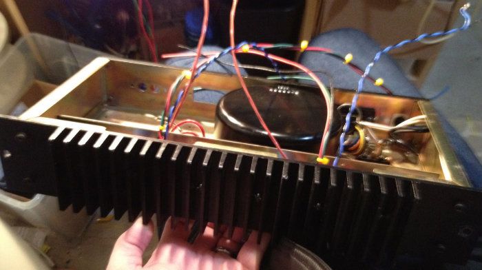
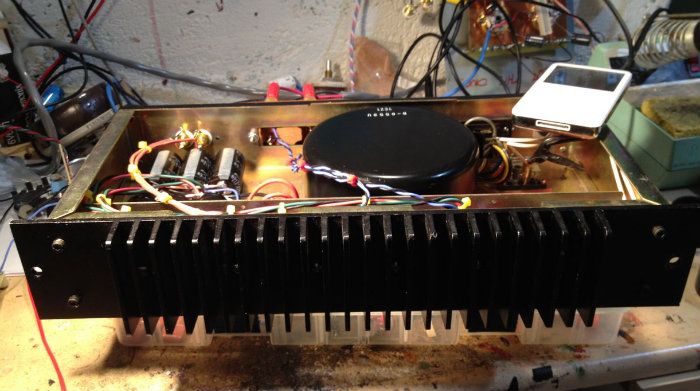
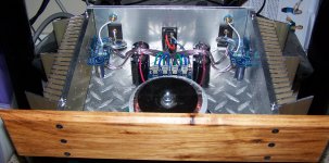
They are Panasonic TS-HA's there are no "vents".
There is a bit of hot glue placed dead center on the bottom and a bit more than that dead center between them holding the power links going to the amps.
Both are placed on a high spot on the diamond plate tread to give airflow to the underside.
The Panasonic FC's that are on the amp boards are actually floating about .5mm above the bottom with a small dab of hot glue on the outside edge of one of them for stability.
The lead end of them has a rubber vent buffer built in for proper spacing.
Last edited:
They are Panasonic TS-HA's there are no "vents".
There is a bit of hot glue placed dead center on the bottom and a bit more than that dead center between them holding the power links going to the amps.
Both are placed on a high spot on the diamond plate tread to give airflow to the underside.
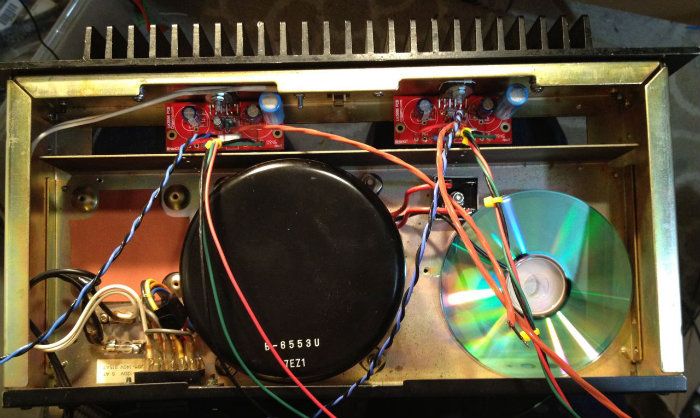
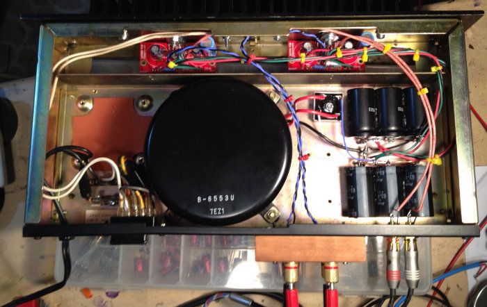
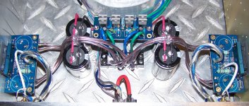
The caps are fine that way, I would just get the voltages from the end of caps not from middle (power supply). also Why do you have so many wires coming out from power supply?
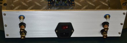
The 4 large caps use 14awg solid black & red for the inputs on the bottom of the PS board.
The voltage outputs (blue & green) go down to a barrier strip.
The amp power outputs come from the other side of the barrier strip with the "clear" jacket wire.
They merely pass at 90 degrees at the middle of the "bulk" supply capacitors.
The voltage outputs (blue & green) go down to a barrier strip.
The amp power outputs come from the other side of the barrier strip with the "clear" jacket wire.
They merely pass at 90 degrees at the middle of the "bulk" supply capacitors.
Attachments
The 4 large caps use 14awg solid black & red for the inputs on the bottom of the PS board.
The voltage outputs (blue & green) go down to a barrier strip.
The amp power outputs come from the other side of the barrier strip with the "clear" jacket wire.
They merely pass at 90 degrees at the middle of the "bulk" supply capacitors.
ok, check with an ohmmeter in continuity mode, check PG- PG+ CHG, you will see that all of them are one connection.
Mate didn't see the perspex. I suppose that's the aim. Yes good work and I like that little bit of timber in every build. Or something that just makes a build standout a little.The wood is Hickory flooring with 2 coats of Birchwood Casey Grain Filler and 2 coats of Birchwood Casey Gunstock Wax.
The top is clear plexi, I installed a 10mcd Red LED on the bottom of the PS with 2kΩ resistor on top, you can see the 4 stack of 8.2kΩ resistors in the middle of the PS.
The LED reflects off of the diamond plate concealed by the Toroid for just enough glow to indicate it's on.
I have those modules and wired them parallel also. But I have done nothing with mine.
There should not be continuity from PG+ to PG-.
There are two separate diode bridges and two separate secondaries on the transformer.
:Edit: I see what you are saying the PG+ & PG- share a plane on the amp board.
I will do some more listening tonight but so far I do notice quite a bit more punch in the kick drum over the single chip stereo version.
Last edited:
- Home
- Amplifiers
- Chip Amps
- Chip Amp Photo Gallery