Okay, so I've had a few of Peter Daniel's gainclone kits running for a few months now, and I can't get rid of the hum. It's definately audible through the speaker from the listening position when no source is connected to the amp and gets slightly louder when I connect a source. I've tried rewiring it a couple times now, and I've got it at it's quietest, but I still consider it unacceptable (compared to my Denon receiver hooked up in the same room to the same source and speakers which has no hum unless you have your ear right up the driver and even then, basically negligable).
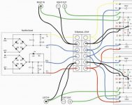
So I'd like some help in troubleshooting this. I have a theoretical background in electronics, but this is the first amp I've built. I've made a diagram showing how I've wired things. I'll take a picture of the actual construction later if need. I built it on a piece of MDF for now.
The first time I used strainded hookup wire, and the newest hookup revision I've used solid core copper. The chips are mounted to heatsinks using mica/thermal compound. You can consider my mains "poor" as the electricity in my neighbourhood is pretty dirty, and the wiring in my house is equally poor, but as noted my Denon amp runs fine.
Suggestions!?!?
-Scott
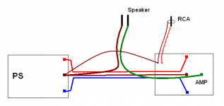
Look how the high current wires are so close to each other, not forming a great loop.
And not just the rails, but also the speaker wires are close to the rails, and to each other.
The signal should go from the RCA directly to the PCB and just after that to the MAIN GND !
Keep the wires really close to each other, and the signal wires far as possible from high currents.
With a layout like this you shouldnt get any hum, I promise !")
But if this doesnt solve your humm, you have something other problem wich doesnt appear on yourt drawing,
like wirings between to two amps, or with using the safety earth a wrong way, or inappropriate shielding, etc.
Good luck !
And not just the rails, but also the speaker wires are close to the rails, and to each other.
The signal should go from the RCA directly to the PCB and just after that to the MAIN GND !
Keep the wires really close to each other, and the signal wires far as possible from high currents.
With a layout like this you shouldnt get any hum, I promise !
But if this doesnt solve your humm, you have something other problem wich doesnt appear on yourt drawing,
like wirings between to two amps, or with using the safety earth a wrong way, or inappropriate shielding, etc.
Good luck !
Attachments
You are missing a connection to earth. Connect the house safety earth wire to the chassis. If you transformer has a metal case also connect this to ground Then connect the PG+ and PG- to that connection. That should take care of the hum.
To test: short the input. You should only hear a quiet hiss which is the residual noise of the system. Try hooking up a battery powered CD player. You should not have any hum. The try a mains CD player. If you have now have hum you have a earth loop. See the article on earthing at http://sound.westhost.com/
Computer audio has an inherently noisy ground. This creates other issures. But that is another thread.
If you have audiosector-pcb, signal-ground(sg) and output-ground(og) are connected at the pcb.If you run wires like in your drawing you are causing groundloop by connecting those two at your wiring-terminal.try running shielded wire from rca-input to sg at pcb and in at pcb.
Klaas
Klaas
billdinva said:Fossil, I think that what is meant by an "isolated ground" is one which the chassis ground and circuit are separated by a ground breaker (resistor and capictor).
The circuit ground needs to be referred to earth otherwise it will float.
what's wrong with floating the DC ground?
As an update...
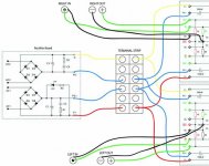
I changed some of the grounds as suggested and things work a lot better now. With no source connected I still get a slight 60 Hz hum, but when I connect a source (only testing with an ipod so far as I don't have another source with a preamp at the moment) the hum goes away and there's just the slight hiss of the noise floor present. I would say I'm quite content now, but thought I would ask if these is common behavior or if there's something I could do to improve things further?
Also, should I be connecting PG+ and PG- together at some point?
Finally, I've attached an updated schematic of my current wiring scheme.
Thanks for the help everyone!
-Scott
Attachments
- Status
- This old topic is closed. If you want to reopen this topic, contact a moderator using the "Report Post" button.
- Home
- Amplifiers
- Chip Amps
- another case of gainclone hum