I would be a bit wary about running the 4780 bridged if you want any real power out of it. At 4 Ohm it gets quite warm, and the package isn't as good as transfering heat as two 3866s. However, if you use a nice big heatsink, 30-35V rails max, and make sure it never drives less than an 8 Ohm speaker then you should be able to get away with it.
jaste said:true, I just hope my elcheapo DMM got a o,1% tolerence....
It's not about absolute accuracy, rather the resolution. Even a cheap 3.5 digit dvm will measure 10K with 10 ohms resolution (10.00). Although there will always be +/-1 digit uncertainty. As a percentage, 10 ohms in 10,000 ohms is 0.1%
Measuring the low-value output resistors is another matter!
Re heat, I agree with PM. Better to bridge with two LM4780s, each running in parallel mode.
CarlosT said:Da**! I've never seen .1% resistors...you guys sure you're not talking about 1%?
Yes, they exist - for example the RC55Y series. And they're expensive - nearly a pound each. But the point is, you don't need to buy them - you'll be able to find enough in a batch of standard 1% components that are well-enough matched.
jaste said:So the low-value output resistor is hard to meashure, maybe I´ll get that one from 0.1% department rigth away tehn, or do the even exist in that tolerance?
I've never seen better than 5% for those, but who knows what's out there given enough cash? Trouble is, at those values, the component leads and PCB tracks have a comparable resistance. I was able to match up components quite well from a batch of 5% parts... I used a current source and voltmeter to make the measurements
")
output resistors
Refer sch at post #34
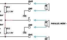
R11 and R12 are output resistors and u will use them for parallel mode operation only. If you want to make a stereo version do not install them.
At no time u should connect all the 3 speakers even if it is shown. U either connect the middle only with R11 and R12 installed or connect the top and bottom speakers(Left and Right) without R11 and R12.
Gajanan Phadte
Refer sch at post #34
R11 and R12 are output resistors and u will use them for parallel mode operation only. If you want to make a stereo version do not install them.
At no time u should connect all the 3 speakers even if it is shown. U either connect the middle only with R11 and R12 installed or connect the top and bottom speakers(Left and Right) without R11 and R12.
Gajanan Phadte
Attachments
Re: output resistors
Indeed.
gmphadte said:At no time u should connect all the 3 speakers even if it is shown.
Indeed.

I today verified that pinkmouse's design still works Made a pcb and at first it didn't work. Turned out the chip/input-ground was not connected to the power supply ground. Maybe I did something wrong with the "ratnest" function but after connecting both power and signal ground, presto, music from my loudspeaker.
I used no zobel due to the fact I didn't have the parts available.
Other parts used;
resistor between input and +in 1 k
resistor between inout and gnd 20k
feedback resistor 20k
-in to gnd 1k
mute resitors, 10k each
mute elco 100uf
psu elco (on pcb) 1000uf and 0.1uf
http://www.zelfbouwaudio.nl/forum/download/file.php?id=35222&mode=view
http://www.zelfbouwaudio.nl/forum/download/file.php?id=35223&mode=view
Made a pcb and at first it didn't work. Turned out the chip/input-ground was not connected to the power supply ground. Maybe I did something wrong with the "ratnest" function but after connecting both power and signal ground, presto, music from my loudspeaker.I used no zobel due to the fact I didn't have the parts available.
Other parts used;
resistor between input and +in 1 k
resistor between inout and gnd 20k
feedback resistor 20k
-in to gnd 1k
mute resitors, 10k each
mute elco 100uf
psu elco (on pcb) 1000uf and 0.1uf
http://www.zelfbouwaudio.nl/forum/download/file.php?id=35222&mode=view
http://www.zelfbouwaudio.nl/forum/download/file.php?id=35223&mode=view
- Status
- This old topic is closed. If you want to reopen this topic, contact a moderator using the "Report Post" button.
- Home
- Amplifiers
- Chip Amps
- Lm4780 SS PCB