Greetings
Ok I correct all errors that I made in SCH file and I think that is now ok")
Here is image file:
http://www.dodaj.rs/f/1Z/bJ/3mXEm1Hs/sch1.png
The resistence of 2R7 need to be 5W wire type?
I have one question for pinkmouse, "That's just a workaround to aid laying out a star ground, if you look at the pcb you can see what I mean." so I need to conect CHNGND to PGND with jumper wire in the middle off PGND1 and PGND2 pad?
Thanks from Serbia
Dragan
Belgrade
Ok I correct all errors that I made in SCH file and I think that is now ok
Here is image file:
http://www.dodaj.rs/f/1Z/bJ/3mXEm1Hs/sch1.png
The resistence of 2R7 need to be 5W wire type?
I have one question for pinkmouse, "That's just a workaround to aid laying out a star ground, if you look at the pcb you can see what I mean." so I need to conect CHNGND to PGND with jumper wire in the middle off PGND1 and PGND2 pad?
Thanks from Serbia
Dragan
Belgrade
tnx
ritvarsrizikovs Great PCB.
pinkmouse
Now I understand what you saing about grounding You are talking about all ground need to be connected to chassiss in one point right? I read about that on this link:
Power Supply & Wiring
I think now the schematic and values are ok and I can start with building this amp. I got 3 peaces of LM4780 and torid transformmer 2x20V 6A so let the building begin
ritvarsrizikovs Great PCB.
pinkmouse
Now I understand what you saing about grounding
You are talking about all ground need to be connected to chassiss in one point right? I read about that on this link:Power Supply & Wiring
I think now the schematic and values are ok and I can start with building this amp. I got 3 peaces of LM4780 and torid transformmer 2x20V 6A so let the building begin
Greetings
Hello again
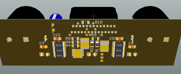
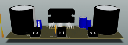
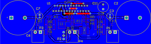
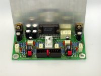
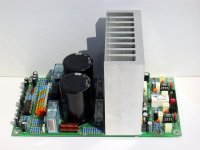
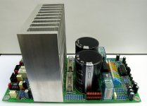
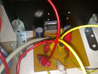
First of all big thanks to pinkmouse for nice PCB that he share.
Here is my work in progrese:
http://www.dodaj.rs/f/2W/JC/3xW0qdTk/draganche0234.jpg
http://www.dodaj.rs/f/1l/MW/4uFebWLi/draganche0238.jpg
http://www.dodaj.rs/f/29/vW/3yl4V6cH/draganche0243.jpg
http://www.dodaj.rs/f/n/n7/28E9S2Io/draganche0244.jpg
http://www.dodaj.rs/f/7/j9/1eyOxUAL/draganche0245.jpg
http://www.dodaj.rs/f/e/mo/4xga1mJJ/draganche0246.jpg
To be continued...
Hello again
First of all big thanks to pinkmouse for nice PCB that he share.
Here is my work in progrese:
An externally hosted image should be here but it was not working when we last tested it.
http://www.dodaj.rs/f/2W/JC/3xW0qdTk/draganche0234.jpg
An externally hosted image should be here but it was not working when we last tested it.
http://www.dodaj.rs/f/1l/MW/4uFebWLi/draganche0238.jpg
An externally hosted image should be here but it was not working when we last tested it.
http://www.dodaj.rs/f/29/vW/3yl4V6cH/draganche0243.jpg
An externally hosted image should be here but it was not working when we last tested it.
http://www.dodaj.rs/f/n/n7/28E9S2Io/draganche0244.jpg
An externally hosted image should be here but it was not working when we last tested it.
http://www.dodaj.rs/f/7/j9/1eyOxUAL/draganche0245.jpg
An externally hosted image should be here but it was not working when we last tested it.
http://www.dodaj.rs/f/e/mo/4xga1mJJ/draganche0246.jpg
To be continued...
Last edited:
LM4780 works!
Hi Al,
I put together your layout and it sings. I am surprised a chip like this produce very nice sound. Bass kicking. Amp is very silent.
Thank you very much.
Raj
Afternoon folks, updated version is now attached. Layout and grounding improved, and dimensions reduced to fit my current application. As always, files in Eagle format, lines on top copper are jumpers. Enjoy.
Hi Al,
I put together your layout and it sings. I am surprised a chip like this produce very nice sound. Bass kicking. Amp is very silent.
Thank you very much.
Raj
Attachments
sorry to impose on your post pinkmouse
ok where to start at the beginning i guess i was up late reading more than usual..thought i was buying one of Brian GT's boards. turns out i didn't.Bad mistake!next time ill know better! Chipamp.com or audiosector from now on!any who bought, 4 pcb"s off ebay wrong ones and on top thought i was only buying 2 lol,no more late night e bay ventures for me.even the chips i bought from audiosectors ebay page i bought 8 instead of 4 by accident lol ill use them it gives me a chance to compare boards now ill buy 1from Peter and 1 from Brian do some comparisons im sure they are very closely matched in caricature ,with my speakers i doubt i will not be able to tell a difference.for me its a fun hobby not to serious about the best quality this the best quality that as long as it sounds decent with no grounding issues I'm fine.which so far knock on wood one 5channel lm3886 surround sound system with separate sub woofer lm3886 x3 in parallel you guys taught me a great deal from reading your post"s especially Andrew T i appreciate what members are doing here this is perhaps the best forum ive had the pleasure to belong to . i highly recommend it to all my friends cheers to all an Happy Holidays>http://www.bing.com/search?q=caricature&FORM=AWRE
ok where to start at the beginning i guess i was up late reading more than usual..thought i was buying one of Brian GT's boards. turns out i didn't.Bad mistake!next time ill know better! Chipamp.com or audiosector from now on!any who bought, 4 pcb"s off ebay wrong ones and on top thought i was only buying 2 lol,no more late night e bay ventures for me.even the chips i bought from audiosectors ebay page i bought 8 instead of 4 by accident lol ill use them it gives me a chance to compare boards now ill buy 1from Peter and 1 from Brian do some comparisons im sure they are very closely matched in caricature ,with my speakers i doubt i will not be able to tell a difference.for me its a fun hobby not to serious about the best quality this the best quality that as long as it sounds decent with no grounding issues I'm fine.which so far knock on wood one 5channel lm3886 surround sound system with separate sub woofer lm3886 x3 in parallel you guys taught me a great deal from reading your post"s especially Andrew T i appreciate what members are doing here this is perhaps the best forum ive had the pleasure to belong to . i highly recommend it to all my friends cheers to all an Happy Holidays>http://www.bing.com/search?q=caricature&FORM=AWRE
ebay
sorry for that pinkmouse but no i was talking about baords i bought by accident. ill send a post.thought they were brians pcb's actually maybe you can help.any suggestions i would appreciate.especially on which way the resistors face on out put i thing they go dales up toward chip 22k down. on input i think down up down up no real support from vendors diyhifinet really wish i didn;order these at 3 a.m on apex jr's site brians pcb is red no mistakes next time p.s are your pcb's for sale?
sorry for that pinkmouse but no i was talking about baords i bought by accident. ill send a post.thought they were brians pcb's actually maybe you can help.any suggestions i would appreciate.especially on which way the resistors face on out put i thing they go dales up toward chip 22k down. on input i think down up down up no real support from vendors diyhifinet really wish i didn;order these at 3 a.m on apex jr's site brians pcb is red no mistakes next time p.s are your pcb's for sale?
An externally hosted image should be here but it was not working when we last tested it.
An externally hosted image should be here but it was not working when we last tested it.
An externally hosted image should be here but it was not working when we last tested it.
resistors
sorry the reason i ask is im second guessing my self. every pic i have seen of this pcb, in completion the resistors are in different arrangements,. some are all up some are up and down. it's become confusing. any how from what i guess, from schematic the 1kr on out put face towards chip, 22k away towards out put... input .. from left to right= R1upR2up R3upR4down. i know this wrong terminology because the flow of resistance shows clearly on schema... but i"m tired and can't concentrate more than five minutes at a time .why don't they just print the damn thing the way it goes: lol ....i used to be a smart monkey know i'm just content throwing things..
sorry the reason i ask is im second guessing my self. every pic i have seen of this pcb, in completion the resistors are in different arrangements,. some are all up some are up and down. it's become confusing. any how from what i guess, from schematic the 1kr on out put face towards chip, 22k away towards out put... input .. from left to right= R1upR2up R3upR4down. i know this wrong terminology because the flow of resistance shows clearly on schema... but i"m tired and can't concentrate more than five minutes at a time .why don't they just print the damn thing the way it goes: lol ....i used to be a smart monkey know i'm just content throwing things..
Afternoon folks, updated version is now attached. Layout and grounding improved, and dimensions reduced to fit my current application. As always, files in Eagle format, lines on top copper are jumpers. Enjoy.
thanks for sharing.
Best regards Sergio.


- Status
- This old topic is closed. If you want to reopen this topic, contact a moderator using the "Report Post" button.
- Home
- Amplifiers
- Chip Amps
- Lm4780 SS PCB