I'm currently deciding on a chassis for my chipamp, and I'm wondering how close together it's okay to put my toroidal transformer, and my audio circuit. Is 1.5" too close? (from edge of transformer to edge of circuit) How about 4.5"?
Also, is it any worse for the audio chip itself to be close to the transformer, than any other part of the circuit?
And in another thread, someone suggested that it's bad for a toroidal to be too close to a wall of the chassis. Is this true?
Thanks for your help!
Also, is it any worse for the audio chip itself to be close to the transformer, than any other part of the circuit?
And in another thread, someone suggested that it's bad for a toroidal to be too close to a wall of the chassis. Is this true?
Thanks for your help!
I have serious problems with toroids. Yes, inducing hum.
So I encase them in a can (I use 35 bulk cans made by Kodak...). This helps somewhat.
-- also putting the toroid on a piece of wood and connecting this with grommets (little rubber holes) to the chassis reduces vibration.
So I encase them in a can (I use 35 bulk cans made by Kodak...). This helps somewhat.
-- also putting the toroid on a piece of wood and connecting this with grommets (little rubber holes) to the chassis reduces vibration.
gaplessophile said:I'm currently deciding on a chassis for my chipamp, and I'm wondering how close together it's okay to put my toroidal transformer, and my audio circuit.
You can always put an earthed wall between the two. Some commercial amps use the heat-sink as shielding.
And in another thread, someone suggested that it's bad for a toroidal to be too close to a wall of the chassis.
In what way? As triode_al says, he cans his toroids which is pretty damn close to being walled in. My Rotel amp also has the toroid as-supplied in a metal can.
I have the edge of my 400VA Toroid 3.25 in away from the sides of the PCBs and about 5.5 in from the centre of the LM3886s.
The amp is dead quiet.
I used the space between the T/F and PCBs for some ventilation holes in the bottom cover.
If you're concerned about T/F vibration you could use Deflex Toroid supports from Partsconnexion.
Non-magnetic materials such as aluminium and stainless steel are preferred for cases, though steel is still used.
I used an aluminium case, with the T/F 1in away from a wooden front panel.
Good luck with your project!
Audie.
In my experience whether or not a circuit (amp or preamp) is suceptable to hum is based primarily on it's layout; specifically, the ground return/reference to the circuit. To pickup the 50/60hz radiated from the transformer the circuit needs a loop to develop the noise voltage across. Careful implementation of the input grounding will eliminate this.
For example, create a ground reference at the transformer by taking the transformer ground directly to the chassis and use the chassis as the ground path to the input jacks; while at the same time locating either the board or the jacks to keep as short a distance between the jacks and the PCB input/ground terminals (within reason, I don't have any problems up to 12"). Use a twisted pair of 20 or 22 gauge hookup wire to provide the best rejection of any magnetic fields. (the speaker grounds and filter grounds are taken from the same ground reference point).
Any noise picked up by either the interconnect cables or amp input leads does not circulate through the input stage but are sunk to the main ground reference of the amp. I use the chassis as a ground because it's a better low impedance path than any wire, especially for RFI picked up by the cables. Obviously good connections are manditory.
As for the chip location relative to the transformer, there is no part of it big enough to develop any appreciable noise signal.
As for the chassis, yes you can develop noise currents, but as long as these currents do not have a path back through the signal reference ground they will not appear on the output.
Shielding magnetic fields is very difficult and requires large or complete assemblies that more or less re-route the magnetic field much like a large rock in a river diverts the current creating a shadow so to speak. Magnetic shielding is normally a ferrous metal that get thicker as the field get's stronger. An aluminum heatsink is transparent as far as magnetic fields are concerned.
Mike.
Even with torroids in very close proximity to PCBs of amps, I have never had a noise or hum problem. I have had noise problems when the torroidal windings did not have the right tension and where somewhat loose. Changing the transformer sovled the noise problems.
EI transformers are another story altogether.
EI transformers are another story altogether.
Cool, thanks for the replies and advice everyone!
Speaking of grounding, I'm using the PCBs from AudioSector, which are designed to be hooked up so that the ground connections from the two rectifier bridges only meet at the ground planes of each chipamp channel. Ie, on the board which has the two rectifiers, the 0v output of one is not connected with the 0v output of the other. Is this a good thing to do?
And MikeBettinger, when you described "taking the transformer ground directly to the chassis", do you mean the 0v output of each of the transformer secondaries? Or the 0v output of the two rectifier bridges?
If I ground everything properly, do you think 1.5" would be too close for a 160VA toroidal and the PCBs?
And one last question, when twisting a pair of wires, does it matter which way you twist them? I wonder because of the direction of the induced magnetic field as current passes down one of the wires.
Thank you!
Whatever is the post rectified power reference is what I'm talking about. I prefer one rectifier and the transformer windings brought out separately to a common chassis ground point, but some use separate bridge rectifiers for each half of the secondaries. I would be interested in the logic of doing this (seriously). It seems to me that I'd rather have my reference be copper wire over the current flowing through a diode junction.
I don't see any issues with the transformer that close but this hobby is all about building, seeing what happens and then building again.
The direction of the twisted pair does not matter, it's the relationship of the wires to each other that counts not the external field. You're minimizing the open loop area (the sensitive part) by doing this.
Mike
Oh wow, somehow I missed the option of using just one rectifier bridge and connecting a wire from each of the secondaries together to form the 0v rail. Is this generally considered to be superior to using two rectifier bridges?
I considered making an external PSU, but decided to put it in the same chassis for compactness.
Thanks again for the help")
I considered making an external PSU, but decided to put it in the same chassis for compactness.
Thanks again for the help
I assume we are talking about a plus and minus supply with a transformer with two equal secondaries. If that is the case the negative output of the first can be connected to the positive of the second and the other two can connect to the inputs of the bridge. It's a normal option.
Cool, thanks Mike
About your description of how an amp should be grounded, could you explain why it's good for the input jacks to be grounded to the chassis, if the transformer is also? I've read about how it's good to keep the signal ground and the power ground separate. Also, with the input jacks grounded this way, should they still have a ground wire going from them to the amplification circuit, along with the signal wire?
Thanks again, this is all extremely helpful.
MikeBettinger said:Shielding works for electric fields but not magnetic fields. Minimising the "antennas" in yor design and shunting the signal around the circuit is the only thing that works.
Mike.
You can shield the magnetic field with mumental.
You can make a case(best cylindrical or spherical) to shield your trafo, mumental in the inside and aluminium connected to the ground in the outside, this will give a good attenuation of the magnectic field.
It's true that you can't shield the magnetic field by 100% but you can attenuate a good amount of it.
Banned
Joined 2002
I'm glad i found this thread. I'm actually working on a aleph mini for a friend that has humm. He is running a set of fostex speakers 94db really efficient so he likes the mini a's but they are picking up some hum from something It's not a grounding problem as we isolated that. What i think i might do is go to a metal store and get a 5" piece of thin steel to shield the toroidal transformer.
Just a question should i use copper or Steel ? Should i get a top welded on top too to have it like a upside down cup ?
Just a question should i use copper or Steel ? Should i get a top welded on top too to have it like a upside down cup ?
Hi,
If this piece of equipment with an earthed (safety ground) RCA ground is connected to another piece of similarly earthed equipment, you are building an earth loop. This will cause hum.
The Chassis and mains earth are connected together to form the safety ground. On very rare occasions are the signal and power grounds connected to the safety ground. generally they are kept separate.
I can explain why this is NOT a good idea.could you explain why it's good for the input jacks to be grounded to the chassis
If this piece of equipment with an earthed (safety ground) RCA ground is connected to another piece of similarly earthed equipment, you are building an earth loop. This will cause hum.
The Chassis and mains earth are connected together to form the safety ground. On very rare occasions are the signal and power grounds connected to the safety ground. generally they are kept separate.
gaplessophile said:Oh wow, somehow I missed the option of using just one rectifier bridge and connecting a wire from each of the secondaries together to form the 0v rail. Is this generally considered to be superior to using two rectifier bridges?
There's a decent case for 2 bridges if you're going to regulate the supply; identical regulators can be used on each positive line before tying one to the other's negative to form your + 0 -.
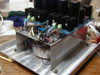
Ain't pretty, but dead quiet...
On my A30/Mini, I shielded the toroids using a stainless sheet metal enclosure. To the inside of that hat, I applied double stick tape and lined the hat with some leftover galvanized flashing material covered by single sided aluminum tape to make it pretty. It's VERY quiet.
On my A30/Mini, I shielded the toroids using a stainless sheet metal enclosure. To the inside of that hat, I applied double stick tape and lined the hat with some leftover galvanized flashing material covered by single sided aluminum tape to make it pretty. It's VERY quiet.
Attachments
- Status
- This old topic is closed. If you want to reopen this topic, contact a moderator using the "Report Post" button.
- Home
- Amplifiers
- Chip Amps
- What distance should a toroidal be from the audio circuit?