Need some help regarding my gain clone:
I've built my amp based on PD's premium kit and it has been running for some time now using only a passive 10K Alps pot between my CD and the amp. However, this weekend I tried a preamp with my setup (Rotel 980) and suddenly got a humming noise, quite audible when nothing is playing. A few details/remarks on my setup:
- For convience I didn't remove my Alps pot from my setup, simply turned it way up (resistance=0)
- The hum is independant of the volume setting on the preamp, but it does quiet down alot if I turn my Alps pot down
- The Alps pot is part metal and parts plastic, if I put my finger on the metal cover on the pot the hum changes in character
- I did not experience any hum or other noises before using the preamp (and turning my pot all the way up)
- I have two boxes made out of oak for the amp, one for the PSU and one for the actual amp. The distance between the boxes does not seem to change anything
- Like many others I have not twisted any of the cables in my power amp
I quess it sound like some kind of grounding problem but to the best of my knowledge everything is correctly connected ... any thoughts?
A second question: The Rotel preamp seems to have some gain, because I can't turn the volume control up much, if my Alps pot has 0 resistance, before it gets way to loud. For such a setup, should I change the gain on my power amp or how does one go about this?
M.A.
Internal cables
Some further explanation concerning cables in my amp:
Since I an using wooden chassis, there is no common grounding by the chassi. Each amp PCB is connected to its own RCA connector and its own power connector. I use one rectifier board for each channel. Only one transformer though, dual secs.
I use Audioquest signal cable internaly in my amp. From the RCA-chassi connectors I use separate cables for signal and ground, the shield is unused in each cable. I had to do this because the cable was not flexible enough and it caused me problems otherwize, using the shield as ground, when soldering the cables to the pot. However, from the pot to the amp PCB, I use one cable per channel using the shield as ground.
I'm not sure if shield is the right word here thuogh. The Audioquest cable is shielded with two wires inside the actual metal foil shield. One of these two wires is in the center and the second (the one I referred to as shield) runs outside the center isolation but within the metal foil shield.
M.A.
What I have learned so far ... need confirmation
Well, I have continued to search the forum for an answer to my problem. However, it is generally very difficult to search and find specific information here. Since I'm not experienced in working with main voltage and such I don't feel up to experimenting much, safety is always a great concern of mine.
This if what I have learned so far:
- I should make some kind of 'star ground' arrangement, connecting AC-ground with chassis-ground for the two amp-boards. But I'm afraid I just don't get it, where can I find AC-ground? What is ground really, the wall socket plug can be turned either way ...
- One should separate power ground and signal ground as much as possible, eg thicker wire to power ground ...
- If the CHG connectors on my amp boards (audiosector LM3875 boards) is power ground, then I should connect these two together, then connect this to the signal ground.
- Signal ground is the ground for the RCAs and the binding posts connected all together.
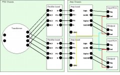
I've made a simple illustration below of my system, all the black connectors are in place now. As I understand it all the colored connectors should be implemented, the yellow and orange wires should be thicker than the rest.
Is all this correct?
I would be grateful for all the help I can get here before I dig in and implement the grounding scheme.
/M.A.
Well, I have continued to search the forum for an answer to my problem. However, it is generally very difficult to search and find specific information here. Since I'm not experienced in working with main voltage and such I don't feel up to experimenting much, safety is always a great concern of mine.
This if what I have learned so far:
- I should make some kind of 'star ground' arrangement, connecting AC-ground with chassis-ground for the two amp-boards. But I'm afraid I just don't get it, where can I find AC-ground? What is ground really, the wall socket plug can be turned either way ...
- One should separate power ground and signal ground as much as possible, eg thicker wire to power ground ...
- If the CHG connectors on my amp boards (audiosector LM3875 boards) is power ground, then I should connect these two together, then connect this to the signal ground.
- Signal ground is the ground for the RCAs and the binding posts connected all together.
I've made a simple illustration below of my system, all the black connectors are in place now. As I understand it all the colored connectors should be implemented, the yellow and orange wires should be thicker than the rest.
Is all this correct?
I would be grateful for all the help I can get here before I dig in and implement the grounding scheme.
/M.A.
Attachments
Hej!, you should not mix the speaker ground with the input ground. Connect the channels only in one place.
A hint to Peter or Brian, why don't you draw up a reference setup for stereo in your manual? Most questions are about the grounding technique.
http://chipamp.com/nigc_kit-users_guide.pdf
Mac Mr yopu have a groundloop, try to eliminate it.
Just an other thing since you live in Gotheburg. DIY meeting soon. Check out the link below.
http://www.diyaudio.com/forums/showthread.php?s=&threadid=75814&highlight=
Hi,
I don't know your chipamp.
Looking at your layout I can see too many connections to ground.
Remove the red wires connecting signal input ground to speaker return. Just as Peranders said.
Why are there two (Pg+ and PG-) ground connections between rectifiers and amp board? Is there a central star ground on board the PCB?
What is ChG? Why is it connected to speaker return and then speaker return to OUTGND? Could ChG be intended for chassis ground which you do not have?
You have insulated chassis (wood). You do not need a safety earth even though you do not have a double insulated system.
If there are any external metal components that could touch mains supply or could become live if the transformer shorted out internally then these components need a safety earth.
I think you have said that you have a 2 prong mains outlet plug running at European 220Vac. I did not realise this existed. I know that this system exists in the US (and maybe Canada) but at the lower 110Vac. A metal chassis or other external conductive parts must be connected to safety earth. If you build a mains operated device then you must comply with this. You would need to run a separate earthing wire back to mains safety earth. Your 2 prong plugs make this extra wire a great inconvenience. You need to make a decision. Buy only double insulated equipment and give up DIY or convert to a more convenient (and safer) 3 wire system.
Board layout
Thanks. I will not consider connecting output and signal-ground.
About the CHG: Yes, I thought I didn't need to connect CHG due to my wooden chassis.
I beleive the CHG, PG+, PG-, OutGND and InGND are all connected on the amp-board. Check out board layout at www.audiosector.com/images/lm3875_se_pcb.gif
M.A.
[\B]
AndrewT said:Hi,
I don't know your chipamp.
Looking at your layout I can see too many connections to ground.
Remove the red wires connecting signal input ground to speaker return. Just as Peranders said.
Why are there two (Pg+ and PG-) ground connections between rectifiers and amp board? Is there a central star ground on board the PCB?
What is ChG? Why is it connected to speaker return and then speaker return to OUTGND? Could ChG be intended for chassis ground which you do not have?
You have insulated chassis (wood). You do not need a safety earth even though you do not have a double insulated system.
If there are any external metal components that could touch mains supply or could become live if the transformer shorted out internally then these components need a safety earth.
I think you have said that you have a 2 prong mains outlet plug running at European 220Vac. I did not realise this existed. I know that this system exists in the US (and maybe Canada) but at the lower 110Vac. A metal chassis or other external conductive parts must be connected to safety earth. If you build a mains operated device then you must comply with this. You would need to run a separate earthing wire back to mains safety earth. Your 2 prong plugs make this extra wire a great inconvenience. You need to make a decision. Buy only double insulated equipment and give up DIY or convert to a more convenient (and safer) 3 wire system.
This is of interest to me also. My lm3886 kit from chipamp.com is configured just like the picture but without the colored chassis connections. The amp board connects all grounds together.
The slight hum I get is improved, but not eliminated, by connecting the two channels together (yellow line).
The slight hum I get is improved, but not eliminated, by connecting the two channels together (yellow line).
The hum is now gone!
The solution turned out to be very simple.
This weekend I removed the redundant pot, shortened some wires and connected the CHG-connectors on the two amp boards (yellow wire). The hum disappeared completely. If I put my ear to the tweeter I can here only a slight hiss type sound, but it is not normally audible, and it could come from the preamp as well as from my power amp I suppose.
Thanks for your help.
M.A.
Mac,
Could you clarify your final position. Did you remove all coloured ground connections except for the connection between the two CHG on the amp boards?
Do you get hum/more hum without the connection between the boards (as I am experiencing).
If so, this makes your findings more or less the same as my single trafo/dual PS configuration except for the degree of 'slight hum'.
PS. I built a chipamp.com 3875 in standard stereo configuration this weekend. There is hum audible at 6inch which is better than the dual ps 3886. I will buils a 3875 in dual ps configuration next.
Current wiring
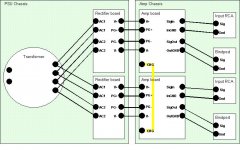
Well, I never implemented any of the colored connections seen in my sketch to begin with, I added them to the sketch only as possibilities to be discussed.
Right now I have implemented the black and yellow lines only, connecting the two CHG connectors (chassi-gnd) on the two amp boards. This seems to work, my humming sound is gone. Perhaps someone can elaborate on why?
I did do some other smaller adjustments to the wiring while I had the amp apart, shortened a few wires and removed the pot I don't need anymore. Not sure, but I suppose the CHG-connection was the key to removing the hum. I have not tried to remove the CHG-connection after the other adjustments, don't really like to take the amp apart again ...
M.A.
The current wiring:
Attachments
Hi Mac,
I disagree with Digi, keep the two rectifiers. It helps prevent channel interaction and reduces load on the diodes.
I think his reference to chassis ground is an oversight, he's forgotten you have a non conducting case.
But it does occur to me that the two CHG connections should, maybe, not be connected together.
How about a resistor between them? and a parallel switch to short out the resistor if it cures a hum problem with some obscure pre-amp/source input connections.
Or not connected at all, did you try this already?
Channel interaction effected?
Hi,
I get the humming type sound when there is no connection between the two CHG-connectors on the amp boards.
Can you elaborate on why the CHG:s should not be connected? If eg channel interaction could be negatively effected, please let me know. Right now though, I have no other solution to rid myself of the humming sound than connecting the two CHG:s.
What value for a resistor are we talking about if I were to try that option?
Can there be anything obscure about my setup? It seems fairly straight forward and normal to me. No high-end setup though by any means, but it delivers nicely:
- Marantz DV4500
- Rotel 980 preamp
- Mezzo Proteus speakers (DIY from a Tony Gee design)
M.A.
AndrewT said:Hi Mac,
I disagree with Digi, keep the two rectifiers. It helps prevent channel interaction and reduces load on the diodes.
I think his reference to chassis ground is an oversight, he's forgotten you have a non conducting case.
But it does occur to me that the two CHG connections should, maybe, not be connected together.
How about a resistor between them? and a parallel switch to short out the resistor if it cures a hum problem with some obscure pre-amp/source input connections.
Or not connected at all, did you try this already?
Hi,
I get the humming type sound when there is no connection between the two CHG-connectors on the amp boards.
Can you elaborate on why the CHG:s should not be connected? If eg channel interaction could be negatively effected, please let me know. Right now though, I have no other solution to rid myself of the humming sound than connecting the two CHG:s.
What value for a resistor are we talking about if I were to try that option?
Can there be anything obscure about my setup? It seems fairly straight forward and normal to me. No high-end setup though by any means, but it delivers nicely:
- Marantz DV4500
- Rotel 980 preamp
- Mezzo Proteus speakers (DIY from a Tony Gee design)
M.A.
Hi,
I cannot explain why the CHGs need to be connected but you have tried it and it works. You have also proved that it does not work without the connection.
What is CHG connected to on the PCB? It is neither signal ground nor power ground nor speaker return since these already exist.
If you want to experiment further then try a 10r resistor between the CHGs. No guarantees that it will improve things.
- Status
- This old topic is closed. If you want to reopen this topic, contact a moderator using the "Report Post" button.
- Home
- Amplifiers
- Chip Amps
- Hum from my gain clone when using a preamp