I've just started playing around with some DIY audio/electronics and am attempting to start my first project. I was thinking of making a stereo amplifier based on the LM3886.
I've attached my schematics (rough, sorry; I'm not used to CAD, I used TinyCAD).
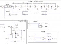
My objectives for the project were to have both RCA inputs and a 1/4" input able to run in stereo to both a regular home stereo jack and also to 1/4" outs (or banana plugs). I was also going to try to put in a bridged mono option where I would send both amplifier outputs to one of the 1/4" outs (or banana plugs).
I'm interested to see if I have totally messed up my circuit (the amp is a copy of many of the amps I have seen and the suggested circuit from the manufacturer's sheet for the LM3886) or if it looks okay. The diodes and capacitors I have on the voltage cascade multiplier will be rated at roughly 25 VAC at least and the capacitors somewhere around 1000 - 2200 uF.
Are my ideas for bridged mono and the single power supply/branching halving voltage okay?
In terms of branching and connecting my wires (I won't be using PCB) together, should I use nylon shells or just solder?
Lastly, when grounding wires, should I send one wire throughout the circuit as the ground then attach that to the case, or attach the individual grounds themselves?
Thanks for your patience. I greatly appreciate your input. It's a great help and it's exciting to fumble around with this new stuff.
Peter
I've attached my schematics (rough, sorry; I'm not used to CAD, I used TinyCAD).
My objectives for the project were to have both RCA inputs and a 1/4" input able to run in stereo to both a regular home stereo jack and also to 1/4" outs (or banana plugs). I was also going to try to put in a bridged mono option where I would send both amplifier outputs to one of the 1/4" outs (or banana plugs).
I'm interested to see if I have totally messed up my circuit (the amp is a copy of many of the amps I have seen and the suggested circuit from the manufacturer's sheet for the LM3886) or if it looks okay. The diodes and capacitors I have on the voltage cascade multiplier will be rated at roughly 25 VAC at least and the capacitors somewhere around 1000 - 2200 uF.
Are my ideas for bridged mono and the single power supply/branching halving voltage okay?
In terms of branching and connecting my wires (I won't be using PCB) together, should I use nylon shells or just solder?
Lastly, when grounding wires, should I send one wire throughout the circuit as the ground then attach that to the case, or attach the individual grounds themselves?
Thanks for your patience. I greatly appreciate your input. It's a great help and it's exciting to fumble around with this new stuff.
Peter
Attachments
[Disclaimer] I am still pretty new to the LM3886 myself, so take everything I say with a little grain of salt, and hopefully somebody else will jump in if I say something wrong!  [/Disclaimer]
Just some initial observation, but the +/-48V seems a little high. The typical voltages that I have seen (and am using) are around +/-35V. If you are using 4 ohm speakers, you may even want to drop that down to +/-30V.
Also, the transformer looks a little on the small side. Why not just go with a 48VCT transformer rated at at least 150 VA? That would simplify the power supply circuit (fewer diodes/caps) and would get you closer to the recommended voltage range of the chips. Also, I am not sure as to the nature of the transformer, but it appears as if it is 0-12, meaning that you don't have a - rail (unless I am missing something in the circuit, which is quite possible!). If you are using a single supply PSU, the app sheet from national has a different circuit topology you should use for the main circuit.
[/Disclaimer]Just some initial observation, but the +/-48V seems a little high. The typical voltages that I have seen (and am using) are around +/-35V. If you are using 4 ohm speakers, you may even want to drop that down to +/-30V.
Also, the transformer looks a little on the small side. Why not just go with a 48VCT transformer rated at at least 150 VA? That would simplify the power supply circuit (fewer diodes/caps) and would get you closer to the recommended voltage range of the chips. Also, I am not sure as to the nature of the transformer, but it appears as if it is 0-12, meaning that you don't have a - rail (unless I am missing something in the circuit, which is quite possible!). If you are using a single supply PSU, the app sheet from national has a different circuit topology you should use for the main circuit.
I don't think that voltage multiplier power supply is going to work at all.
Even if multipliers worked efficiently (Power out = power in) you have multiplied you voltage by 8 or so, thus there will be 1/8 of the current output. Your schema has a 12v 25 ma transformer so expect 3ma out. Don't forget power in watts = amps times volts.
For any real output you might want 3amps output current so your transformer would need to supply 30!!
In reality those multipliers are very inefficient so it's much worse tham that.
Just use a "normal" transformer/rectifier/capacitor PSU.
The PSU voltage does seem very high. 28v is enough if you want to bridge into an 8 ohm speaker.
help with 3886
If you hook up that power supply your chips will go poof! Multiplier circuits are used to produce HV from HV sources, for every diode capacitor leg you will loose current abiltity by about a power of ten.
Then of course you only have a 48V supply and ground you need to have a center tap transformer and even if it was 12V you would need to make a - and + ladder to provide a split supply.
I would strongly suggest going with the ap notes from national they are pretty foolproof.
And going with a standard 25V /25V center tapped transformer at least 160VA.
your amplifier will have 20 gain at DC...you should put a cap between the 1k resistor(the one at the - input) and ground.
This will ensure unity gain at DC.
Capacity >100uF
you should place another resistor to limit the mute curent at 10mA
It's recomended that you should read the documentation about this chip before you start designing.
It will save you from burning some IC-s.
This will ensure unity gain at DC.
Capacity >100uF
you should place another resistor to limit the mute curent at 10mA
It's recomended that you should read the documentation about this chip before you start designing.
It will save you from burning some IC-s.
- Status
- This old topic is closed. If you want to reopen this topic, contact a moderator using the "Report Post" button.
- Home
- Amplifiers
- Chip Amps
- Gainclone Newbie Help LM3886