Hi guys,
I'm building a circuit that has an adjustable gain. The gain is controlled by an opto-resistor. I've attached the schematic.
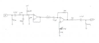
The circuit runs on a single supply, hence the voltage dividers. At the front is a low pass filter, then a buffer, then the inverting gain stage. The opamp I'm using is a OPA2134. +V is around 8.5V.
The circuit works really well on the breadboard, but when I PCB it it oscillates like crazy when the opto-resistor resistances goes into the megaohm range.
If you're looking at the circuit and going "man this guy's green" you're right. I'm pretty new to audio design. If you could provide any suggestions that would help with either the oscillating problem or anything else you might see that's blatantly incorrect, I'd appreciate it.
Thanks,
Steve.
I'm building a circuit that has an adjustable gain. The gain is controlled by an opto-resistor. I've attached the schematic.
The circuit runs on a single supply, hence the voltage dividers. At the front is a low pass filter, then a buffer, then the inverting gain stage. The opamp I'm using is a OPA2134. +V is around 8.5V.
The circuit works really well on the breadboard, but when I PCB it it oscillates like crazy when the opto-resistor resistances goes into the megaohm range.
If you're looking at the circuit and going "man this guy's green" you're right. I'm pretty new to audio design. If you could provide any suggestions that would help with either the oscillating problem or anything else you might see that's blatantly incorrect, I'd appreciate it.
Thanks,
Steve.
Attachments
Hi David,
Do you mean that the opto resistor doesn't behave like a nice resistor when a constant current is fed into the LED, or do you mean that the output resistance of the LDR is nonlinear with respect to the input current?
I'm assuming you mean the latter. The circuit is for a guitar effect. The gain of the circuit doesn't have to be precise. What's most important is that the gain is varying.
As for the oscillating, I cured it by putting a 100pF cap across the 10k feedback resistor. My remaining problem is that control voltages for the opto resistor are showing up in the audio signal. I'm getting a weird "digital" sound when I change the gain.
Thanks for having a look at my circuit Dave.
Steve.
2sb18 said:The circuit works really well on the breadboard, but when I PCB it it oscillates like crazy when the opto-resistor resistances goes into the megaohm range.
If you could provide any suggestions that would help with either the oscillating problem or anything else you might see that's blatantly incorrect, I'd appreciate it.
Maybe first OP-amp does not like being 'unloaded'.
1 MOhm is almost no load.
Try to put a 100 kOhm resistor, from first OP-amp output to the ground.
This way, whatever high value the following, LDR, light dependent resistor will have,
the OP-amp will have 100 kOhm load to work into.
You see such a resistor, 100 kOhm, at the very Output to the right.
.............................
Otherwise.
I would avoid using such high values resistors in any audio circuit.
I see you have 4M7 and 2M2.
I should not use any resistor higher than 1 MOhm.
Not even around OPA2134 which is a JFET input Op-amp.
Besides, 1 MOhm is easy to find, while 2.2 4.7 MOHM is not everywhere.
For example input bias to first OP-Amp ( to set input at 50% of power supply)
could be 1MOhm-1MOhm (not 2M2-2M2)
A couple of things..
1. Put a resistor to ground between the opto-resistor and the 3.3 uF cap.
2. Put a capacitor in parallel with the lower 100k resistor from the + input of the second op amp, to ground. 10 to 100 uF would be good.
3. Your schematic doesn't show any decoupling caps.
4. Not sure, but you may also need a resistor to ground between the 3.3 uF cap and the - input of the second op amp. Or, just get rid of the 3.3 uF cap.
Thanks for your suggestions guys. I tried all of them, my PCB is becoming progressively uglier ") Unfortunately, none of the ideas did anything to squash this control voltage that's getting through. I have a feeling it's a grounding problem. This is because even when the circuit is bypassed (but has it's ground still connected to system ground) you can hear the control voltages.
Unfortunately, none of the ideas did anything to squash this control voltage that's getting through. I have a feeling it's a grounding problem. This is because even when the circuit is bypassed (but has it's ground still connected to system ground) you can hear the control voltages.
The whole circuit has three parts. A PIC microcontroller running at 2MHz connected to an inverting opamp D/A. That's connected to a simple opamp voltage-to-current circuit which controls the opto resistor. The opto resistor draws between 0 and 30mA. Then there's the audio signal circuit that I attached above. Each of the three circuits has it's own LM317 regulator.
Right now I have the power grounds connecting to the signal ground near the LM317 regulator used for the audio circuit. Is there somewhere else where I should be connecting the signal ground?
Thanks,
Steve.
Unfortunately, none of the ideas did anything to squash this control voltage that's getting through. I have a feeling it's a grounding problem. This is because even when the circuit is bypassed (but has it's ground still connected to system ground) you can hear the control voltages.The whole circuit has three parts. A PIC microcontroller running at 2MHz connected to an inverting opamp D/A. That's connected to a simple opamp voltage-to-current circuit which controls the opto resistor. The opto resistor draws between 0 and 30mA. Then there's the audio signal circuit that I attached above. Each of the three circuits has it's own LM317 regulator.
Right now I have the power grounds connecting to the signal ground near the LM317 regulator used for the audio circuit. Is there somewhere else where I should be connecting the signal ground?
Thanks,
Steve.
Using a simple voltage divider to bias the opamps at 1/2 V+ is injecting power supply noise into the audio. You should make a voltage divider with relativly low value resistors (~ 1k to 4.7k), and have a large cap between ground and the divider output (~ 100 to 1000 uF). Use this filtered 1/2 V supply to bias the opamps thru relativly large value resistors (~ 10k to 1M).
A bipolar (+/- 9 to 18 V) supply would be even better.
A bipolar (+/- 9 to 18 V) supply would be even better.
Thanks for the idea Possum. I implemented your filtered voltage divider and although it cut down on white noise it didn't stop this digital noise I'm hearing.
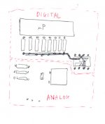
But I think I'm onto something. I've attached the general layout of my pcb. The resistors under the uP are for the inverting op amp D/A which controls the opto resistor. The trace attaching all the resistors is the virtual ground. The resistors go from 10K to 1.3M. I found that when I disabled the outputs going to the 1.3M and 649k resistors, the digital noise was reduced by quite a lot. So I'm guessing that parasitic capacitance is coupling the D/A to the analog section. Is there something that says that bigger resistors causes bigger stray capacitance?
So I'm trying to think of ways to decouple the digital noise from the analog section. I'll try moving the sections farther apart. Maybe use a ground plane too. But if I use a ground plane, should it be on the digital side, or the analog side, or both?
I feel I'm pretty close to a solution. Thanks again guys for all your help.
Steve.
Attachments
- Status
- This old topic is closed. If you want to reopen this topic, contact a moderator using the "Report Post" button.
- Home
- Amplifiers
- Chip Amps
- Opto resistor circuit