Hi all,
After several attempts to build a BPA200 without the DC-servo i finally gave up. . .
Peranders: Thank you for keeping on telling me i should read the appnotes and use the DC servo! This is just the type of nagging i need to keep going!
I am more than a little stubborn...")
Anyway so i thought i should give the DC servo a go.
But i already have these really nice PCB´s from Peter Daniel...
So i decided to play with Eagle and construct a servo add-on pcb.
The pcb i made almost fits perfectly in size to 2 PD pcb´s.
So give me some comments please! Its my 3rd Eagle attempt ever, but dont be nice to me! Be honest!
BR
Nicks
After several attempts to build a BPA200 without the DC-servo i finally gave up. . .
Peranders: Thank you for keeping on telling me i should read the appnotes and use the DC servo! This is just the type of nagging i need to keep going!
I am more than a little stubborn...
Anyway so i thought i should give the DC servo a go.
But i already have these really nice PCB´s from Peter Daniel...
So i decided to play with Eagle and construct a servo add-on pcb.
The pcb i made almost fits perfectly in size to 2 PD pcb´s.
So give me some comments please! Its my 3rd Eagle attempt ever, but dont be nice to me! Be honest!
BR
Nicks
Attachments
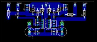
Triden: The cut down version was the first version. But in this version the inp and gain fits with the spacing used on the PD pcb's. Inp fits with out on PD pcb, gain fits where the gap between the gain resistors (22k and 680ohm) is. This pcb is named just as its intended use. Its an "add-on" pcb that fits between 2 amp pcb's for parallell use.
So guys , keep on commenting please!
BR
Nicks
So guys , keep on commenting please!
BR
Nicks
- Status
- This old topic is closed. If you want to reopen this topic, contact a moderator using the "Report Post" button.