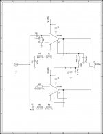
Hi, I'm pretty new to this stuff. I've been looking at building an GC for awhile now. I'd like to get 100w per channel and i need to drive some 8 ohm speakers, so i figured that the best design for this would be the BR100 presented in AN-1192. Attached is what I think is the correct design for this. It would be greatly appreciated of you guys could look over the schematic.
Additionally I have a few questions.
Capacitors C1, C3, and C5 are all filter caps, is it necessary to include these and what values should they be?
I was planning on using the regulated supply on http://myweb.tiscali.co.uk/nuukspot/decdun/gainclone6.html
Would this supply be enough for 2 100w channels and what is a safe VA for the transformer to handle this load?
Thank you all for your help!
Attachments

- Status
- This old topic is closed. If you want to reopen this topic, contact a moderator using the "Report Post" button.