Well... have worked with a typical parallel 4780 (briangt pcb) build with all they typical build (dual secondary toroid transformer).
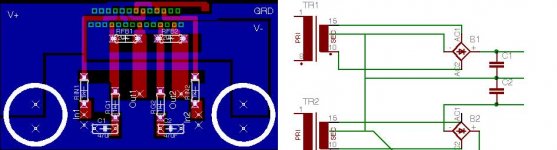
But now, for more learning, using a pair of 18vct transformers, 1 per rail and a single 4780 to use one amp per channel. Using the typical application from NS datasheet, came up with attached pcb.
First... is wiring for PS ok? Grounding center tap and pulling the negative out on rectifier for postive rail to ground. Then also pulling + out of rectifier to ground for the negative rail.
Any suggestions on the pcb layout? Intending to try the iron laser toner method. I'm a bit worried about the 'islands' for the 4780 compact footprint surviving. Will I be fighting an uphill battle? Or do I need to string them together and cut out after etching?
On pcb, left out mute resistor as freeware eagle didn't want me to connect top and bottom layer - can do it manually.
For NS typical application, zobel not needed?
Attachments
1. Ground reference resistor is missing. Need to incorporate that (+ in to ground) or you'll get huge DC-offset.
2. CT can be used unconnected in a pure CT transformer for full voltage (18 VCT can be used as 18 V transformer). No need to connect CT to anything. I am not sure what will happen if you connect CT as shown, I suspect you are generating some kind of short circuit.
Use end taps of transformer to connect to bridges and the rest of the circuit in conventional dual bridge supply as published by Brian, Peter and Carlos. Use whatever suits your fancy, big caps, snubber, or small caps only, as per your choice.
3. Zobel is needed but can mount offboard. Not needed to mount on PCB all the time.
4. Nice layout! Peter/Brian uses elegant solution to mount mute resistor. One negative rail is taken through hole (you can use single trace with punch on both sides) at one NC pin to other side of board (track side) and routed to near the mute pins. Then a pad for the resistor. Have a look at his board. Very simple solution. In a crunch manual mounting will also work, but looks bad on a beautiful board like this.
1 - will be easy to squeeze the in+ to ground. wonder why NS left it out. 22k shunt to ground per input?
2. - so will i just connect - of positive rail BR with + of negative rail BR to form middle point between the PS caps and tie to ground?
3. will zobel values be same as for parallel config, .1uf poly cap with 2.7(2w) resitor?
4. actually derived this layout some from studying the brian layout, some recent post about using planes and studying the pins/datasheet. the reference board seem just too large accounting for on board connectors and such. Hope to give etching a whirl in next few days.
1. Strange, but you're right. It's not there on page 1 of the pdf but in all other examples they include it, even in the refernce PCB it's there. It's 47K that they specify, but 22K is a better value (lower offset with lower values). 1 per input.
2. Yes, pretty much, and leave the CTs hanging.
3. Yes, you can experiment, for my single amp I use 4.7 ohm and .1 because I have those lying around. Upto a point they don't influence the sound - that's subjective though.
4. All the best! It's a nice chip if you're looking for some amount of juice, but for ~60W per channel the 3875 may give better sound and easier to construct...
- Status
- This old topic is closed. If you want to reopen this topic, contact a moderator using the "Report Post" button.