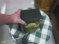
Any of you that have read the dumpster dive thread know by now that I have come across a ~2KVA CT isolation transformer for free! I would love to use this in a psu for the LM4702 based amps I am planning, but the rectified voltage will be higher than what I was aiming for. By my math, I can expect ~+/-85V rails using a "traditional" bridge/cap non-regulated PSU, but for this project I was thinking ~+/-50V would be closer to my target. I would think that using a simple voltage divider would be pretty inefficient ") )), so I am trying to get a few ideas from more experienced power supply builders.
)), so I am trying to get a few ideas from more experienced power supply builders.
AudioFreak suggested a choke input power supply that would pump out ~51V, but I was under the impression (after reading the few internet references I could find, coupled with the fact that I may not know exactly what I am looking for) that this sort of PS was used primarily in tube amps or for higher voltage applications. Would this configuration be appropriate for an LM4702 type system, or is there some other option for getting the voltage from this transformer dropped down a little? Also, I have only come across a couple of schematics for choke input power supplies, and they are for higher voltage supplies (around 4k). If anybody has some suggestions as to whether a design of this type would be appropriate, and where I could read some more to intelligently go about building a power supply, I would greatly appreciate it!
Thanks!
David
)), so I am trying to get a few ideas from more experienced power supply builders. AudioFreak suggested a choke input power supply that would pump out ~51V, but I was under the impression (after reading the few internet references I could find, coupled with the fact that I may not know exactly what I am looking for) that this sort of PS was used primarily in tube amps or for higher voltage applications. Would this configuration be appropriate for an LM4702 type system, or is there some other option for getting the voltage from this transformer dropped down a little? Also, I have only come across a couple of schematics for choke input power supplies, and they are for higher voltage supplies (around 4k). If anybody has some suggestions as to whether a design of this type would be appropriate, and where I could read some more to intelligently go about building a power supply, I would greatly appreciate it!
Thanks!
David
Hi,
try splitting the turns to give less voltage, about half voltage in each. Then add more turns to each winding to bring each of them up to the voltage you want. Use the same wire thickness.
You will end up with four secondaries. Run two secondaries into one rectifier for the left channel. Run the other two secondaries to another rectifier for the right channel.
When using regulated power supply for power amp
best NOT to have too much voltage drop across Regulator.
In other words,
if your power amp needs 50 Volt DC, get a transformer that fits.
Something like 7-12 Volts for the regulator
would give a transformer that have 57-62 Volt DC output.
best NOT to have too much voltage drop across Regulator.
In other words,
if your power amp needs 50 Volt DC, get a transformer that fits.
Something like 7-12 Volts for the regulator
would give a transformer that have 57-62 Volt DC output.
The only practical solution that comes to my mind now is a siwtching regulator, either a 100Hz thyristor controlled one to chop the 50Hz sine wave (similar to the ones found in Carver amplifiers), or a HF buck regulator (plain SMPS stuff, but then again, the 50Hz transformer may be also discarded in favour of a HF one).
###########################################
Forget what I said below, like I said I am tired. However this may
be of some interest. Here are some basic rules for resistive,
capacitive and inductive voltage dividers. It is possible that one of
these may be of some use.
I spoke before I thought it through, I can do that very well
sometimes
###########################################
Well lets make an assumption (I know its not good to '***-u-me' anything) that ~42VDC would do the job. What about capacitively coupling between the +VDC and 0VDC for positive, then between -VDC and 0VDC for the negative? Looks like it would get around the problem of not being able to 'adjust' the windings (if in fact that is a problem with his transformer) and much more efficient than the voltage divider. It should only require four capacitors but I do not have any figures for what the specs should be.
---------------o +
|
=
|
-----------------------------o 1/2 +
|
=
|
---------------o 0
|
=
|
-----------------------------o 1/2 -
|
=
|
---------------o -
Seem reasonable? It's late and I'm tired.
(looks like it took out my white space but my simple diagram should still be legible)
THe multiplier for a capacitive input power supply is 1.414
minus diode drops. We are all very familiar with this one.
The multiplier for Choke input is 0.90 minus diode drops.
Seems to me this puts it right where you want to although you could get a further drop by series connecting diodes if needed.
I do not believe this is only for high voltage power supplies.
The only downside is you would have to buy 2 chokes but you would have a PS of superior regulation.
Audio freak was right
I can't think of any reason that a choke input supply couldn't be used here (but I can't think of everything ) The reason they are more common in tube amps probably has as much to do with era than anything else. They provide good regulation without active regulation, but these days (and at lower voltages) I suspect that active regulation is cheaper and looks better on paper. OTOH, in the case of tube amps I have found that a simple choke input supply usually sounds better. Chip amps seem to respond well to simpler supplies, so I suspect that they might sound better with choke input than active regulation. (I won't pretend to understand why, but that doesn't keep me from using the knowledge.)
Anyway, there are a couple of criteria that need to be met in order to keep a choke input supply from acting like a cap input supply. In other words, to keep the voltage from rising. In technical terms, you need to keep the diodes conducting during a full 180 degrees of each 60Hz cycle. If they conduct only during part of the cycle to keep the caps charged then the supply voltage will go up as it starts to act like a cap input.
In practical terms, it means that you need to makes sure the choke is big enough and that you always draw enough current. The old rule of thumb is that the inductance of the choke needs to be at least:
L > V/I
where I is in milliamps (a throwback to high voltage, low current supplies.) Anyway, you can see that if you draw more current (bigger I) then you can get away with a smaller choke.
As an example, with V=50 and I = 500mA you need a choke that is at least
L > 50/500 = .1 henry or 100mH
Typically, if your choke is close to the lower limit then you would want to add bleed resistors from each rail to ground to make sure that the minimum current is always being drawn from the supply.
You could use one choke between the center tap and ground. You could use two chokes, one in each rail (the inductances will add) or you could use a dual winding choke with one winding in each rail.
Hope that's enough to get you started thinking at least.
-- Dave
) The reason they are more common in tube amps probably has as much to do with era than anything else. They provide good regulation without active regulation, but these days (and at lower voltages) I suspect that active regulation is cheaper and looks better on paper. OTOH, in the case of tube amps I have found that a simple choke input supply usually sounds better. Chip amps seem to respond well to simpler supplies, so I suspect that they might sound better with choke input than active regulation. (I won't pretend to understand why, but that doesn't keep me from using the knowledge.)Anyway, there are a couple of criteria that need to be met in order to keep a choke input supply from acting like a cap input supply. In other words, to keep the voltage from rising. In technical terms, you need to keep the diodes conducting during a full 180 degrees of each 60Hz cycle. If they conduct only during part of the cycle to keep the caps charged then the supply voltage will go up as it starts to act like a cap input.
In practical terms, it means that you need to makes sure the choke is big enough and that you always draw enough current. The old rule of thumb is that the inductance of the choke needs to be at least:
L > V/I
where I is in milliamps (a throwback to high voltage, low current supplies.) Anyway, you can see that if you draw more current (bigger I) then you can get away with a smaller choke.
As an example, with V=50 and I = 500mA you need a choke that is at least
L > 50/500 = .1 henry or 100mH
Typically, if your choke is close to the lower limit then you would want to add bleed resistors from each rail to ground to make sure that the minimum current is always being drawn from the supply.
You could use one choke between the center tap and ground. You could use two chokes, one in each rail (the inductances will add) or you could use a dual winding choke with one winding in each rail.
Hope that's enough to get you started thinking at least.
-- Dave
DAve :
good point about puttingchoke in centre tap.
"Typically, if your choke is close to the lower limit then you would want to add bleed resistors from each rail to ground to make sure that the minimum current is always being drawn from the supply."
This may be very obvious but to underline the above: the bleeder has to be past the choke in order to maintain the current in the choke.
I once built a 5V 50A linear psu with a choke filter.
Choke filter psus give better regulation than the usual capacitor style and run the transformer and bridge much cooler.
The real advantage is the strong filtering action getting rid of those 100/120Hz harmonics and the rf crud on the mains.
Choke filter psus give better regulation than the usual capacitor style and run the transformer and bridge much cooler.
The real advantage is the strong filtering action getting rid of those 100/120Hz harmonics and the rf crud on the mains.
If I were buying a new one, I would.lineup said:In other words, if your power amp needs 50 Volt DC, get a transformer that fits.
Dumpster dive has presented me with a challenge! Now it is a matter of finding the right scalpel or sledge hammer to make it work.

This is just what I wanted to hear! I guess we will see whether this is indeed a good design for chipamps (if you can even call the LM4702 a chipamp--more of a hybrid IMHO). I will be sure to run a preliminary circuit by the board before building/ordering parts, but I think it is time I committed some serious time to understanding this circuit and making sure I have a good design.Dave Cigna said:They provide good regulation without active regulation. . . . Chip amps seem to respond well to simpler supplies, so I suspect that they might sound better with choke input than active regulation. . .
Thanks for the insight, Dave.
If all you want to do is lower the voltage all you have to do is put some extra turns of wire onto the secondary. Wind them opposite the direction of the existing secondary windings. The voltage induced in the new coil (-X volts) will add to the voltage in the original (+Y volts) and you'll get lower voltage out.
I_F
I_F
Well, that isn't going to be as easy as one would like. I would rather modify the PSU design than the transformer.I_Forgot said:If all you want to do is lower the voltage all you have to do is put some extra turns of wire onto the secondary.
Attachments
Power supply challenge
Shunt off some voltage, every ohm = about 10% voltage drop, use none inductive current sense power resistors.
Your power supply is close, you can safely run +/- 35VDC easily.
Use your bridge rectifier small filter caps the you're shunts then final filter storage and by-pass caps.
Shunt off some voltage, every ohm = about 10% voltage drop, use none inductive current sense power resistors.
Your power supply is close, you can safely run +/- 35VDC easily.
Use your bridge rectifier small filter caps the you're shunts then final filter storage and by-pass caps.
I'm a newbie, so I'd take the absolute simple approach.
You still want the full voltage for your output power darlingtons. So make a regular bridge-rectifier plus capacitor bank (sounds like you have an abundance of high voltage capacitors here, so go wild).
Then the LM4702 wants +/- 65V, to be reasonably safe, and will draw a fairly constant 25 to 30 mA current. So take a series resistor from each rail, say 680 ohm 2 watt, to drop approx 20 volts before feeding the chip's power. (680o will drop 17 volts at 25mA, and dissipate half a watt).
Add another 2200u per rail to decouple the chip's supply - the ripple will be absolutely minuscule at that point.
- Status
- This old topic is closed. If you want to reopen this topic, contact a moderator using the "Report Post" button.
- Home
- Amplifiers
- Chip Amps
- Power supply design challenge!