Hi Sono,
If before the cap, then it references the input side of the cap to ground and may be in the high k or low M range.
If after the cap then it forms the high pass filter that attenutaes the signal before entering the gain stages of the amplifier. This is likely to be mid to high k.
that resistor could be before the DC blocking capacitor or after.The resistor 'bleeds' the signal from this point to earth.
If before the cap, then it references the input side of the cap to ground and may be in the high k or low M range.
If after the cap then it forms the high pass filter that attenutaes the signal before entering the gain stages of the amplifier. This is likely to be mid to high k.
where are you recommending adding this resistor?4.7-6.8 ohm
are you sure? I thought Cyrus had a low pass filter before the gain stages.Cyrus 1 which has direct input from the RCA's to the blocking capacitor on the main power amps with no resistor directly in signal
Hi Andrew,
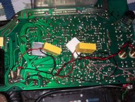
Please find an image attached showing exactly what's happening in this amp.
I've replaced a couple of the original RCAs with gold plated ones (though I'm no great fan) and taken the signal from here direct to C31, which is a 2.2uF non-polar on the original amp. I've replaced it with a 1.8uF MKT for the moment.
The signal is bleed-off through a resistor to ground near where the pot used to be.
The higher the resistor value, the more music, so resistor values of 4.7-6.8 ohm appear to give about the right volume for me
I've avoided all the input selectors and associate resistos and by having just one volume have probably taken this amp to its minimalist extremes.
I've also tried using an elma switch to allow changes in resistor value and will probably end up using something like that in the end. Values will be from 3.3 to 10 ohms in six steps.
Attachments
If you have a Cyrus schematic or amp lying around try to see what is actually happening.
The resistor values are correct. Can you see that the higher the resistor value the higher the volume?
Another simple way to do this is to put a low value resistor directly across the RCA. The lower the value the more signal is being dumped to earth.
I beleive Russ Andrews has used this technique in his attenuated leads.
Cheers!
sonokeling said:If you have a Cyrus schematic or amp lying around try to see what is actually happening.
The resistor values are correct. Can you see that the higher the resistor value the higher the volume?
Another simple way to do this is to put a low value resistor directly across the RCA. The lower the value the more signal is being dumped to earth.
I beleive Russ Andrews has used this technique in his attenuated leads.
Cheers!
Sounds like you are shorting the output (= dumping the current to ground !?!) forming an attenuator with the output impedance and a small value resistor.
Whatever floats your boat.

Hi Peter, nice project, I've studied stepped attenuators for a while starting with a series type, than went directly to a ladder type attenuator... The laddder sounds much nicer if you'd ask me.
I chose 'dale' resistors and tested some others, but they all must've been good. I don't hear any 'quality' difference between the last- and second to last step, though the last is derectly connected... All steps have such perfect equal level and quality, I've purchased 10 resistors in each value, some values I took 20 pieces and matched them myself....(0.1% tolerance!)...
I'll look up some of the handy information I used back than...
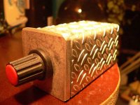
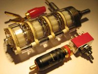
Here's a picture of the series attenuator (my first):
I chose 'dale' resistors and tested some others, but they all must've been good. I don't hear any 'quality' difference between the last- and second to last step, though the last is derectly connected... All steps have such perfect equal level and quality, I've purchased 10 resistors in each value, some values I took 20 pieces and matched them myself....(0.1% tolerance!)...
I'll look up some of the handy information I used back than...
Here's a picture of the series attenuator (my first):
Attachments
Dr. ODD said:any Progress ?
Well, the work on an attenuator has been finally completed.
All credits with regards to control board, display and programing go to Veteran.
The relay board design was our combined effort, the attenuator concept was my idea, however, I was heavily inspired by Placette Audio. We have incorporated few changes though, like completely different layout, use of printed board for relays and resistors mounting and adding additonal 3 steps to lower the control range by another 12db or so.
The steps are also more uniform and the actual value of attenuation is being displayed. Mute function is also included.
An externally hosted image should be here but it was not working when we last tested it.
An externally hosted image should be here but it was not working when we last tested it.
Each channel has its own dedicated board, with SMD realys mounted on both sides:
An externally hosted image should be here but it was not working when we last tested it.
An externally hosted image should be here but it was not working when we last tested it.
For this version I decided to use nude Vishays, you need 28 resistors to complete the task. The PCB also allows the use of Caddocks, which have slightly wider footprint. I gues that type of attenuator will also work well with regular type of resistors.
An externally hosted image should be here but it was not working when we last tested it.
The resistors are mounted in two rows (series and shunt separately), the relays bypass them, depending on attenuation. I wanted to achieve the shortest signal path and it seems like it was the only elegant way to do it. This requires SMD relays though.
An externally hosted image should be here but it was not working when we last tested it.
The two Dale resistors you see here, are to provide -47db, -52db and -58 db steps (in addition to regular steps with use of Vishays)
An externally hosted image should be here but it was not working when we last tested it.
The optical encoder used to control the volume is from HP, the same as the one in ML380. The "feel" is like nothing else
")
An externally hosted image should be here but it was not working when we last tested it.
I still didn't listened to it, I only listened to the sound of relays switching
As I also have a Placette and will be able to compare both.
I won't hide that my intention here was to create the best sounding remote controlled attenuator possible. If it checks out well, I might arrange for silver/teflon in relay switching boards.
The calculator was posted here: http://www.diyaudio.com/forums/showthread.php?postid=840215#post840215 and you can use any resistor values you may choose (however, they need to multiply by 2). This calculator was created by Algar_emi.
The relays are approx $3 ea, nude Vishays are either $11.50 from Percy or $7.50 directly from TI. You can also use Caddocks MK132 at $4ea.
The relay PCBs would be $20/set, the control board with microchip and display need to be sourced from Veteran.
The HP encoder is probably $70, but you can get a cheaper one as well.
At some time in a future, I will be probably offering a complete kit.
This type of attenuator is best to use directly at amp's input. If the product becomes succesful I may consider some nice enclosure, but it's still a long way from this point.
hi peter,
do you have any idea how this relay attenuator handles dc offset? another relay attenuator i use requires the use of coupling capacitors to remove the dc as with a dc offset of only 5 mV it "pops" at steps where all the relays move at once.
i would be very interested in this relay if i allows me to avoid the use of coupling caps. actually, i'm interested either way but the ability to handle some dc offset would be fantastic.
thanks
do you have any idea how this relay attenuator handles dc offset? another relay attenuator i use requires the use of coupling capacitors to remove the dc as with a dc offset of only 5 mV it "pops" at steps where all the relays move at once.
i would be very interested in this relay if i allows me to avoid the use of coupling caps. actually, i'm interested either way
but the ability to handle some dc offset would be fantastic.thanks
Here is the relay datasheet: http://pewa.panasonic.com/pcsd/product/sign/pdf_cat/tq.pdf
As to the attenuator configuration, it is analog to a potentiometer. The good thing about it is that the resistors are not switched in and out, but the chain of resistors (series and shunt) is shorted by relays what reduces switching noise.
The schematic was posted here: http://www.audio.webd.pl/pdf/pvc_sch.pdf
- Status
- This old topic is closed. If you want to reopen this topic, contact a moderator using the "Report Post" button.
- Home
- Amplifiers
- Chip Amps
- In search of a perfect attenuator