Hi guys, I am trying to help out a friend with his project. Both of us are noobs, so right now, it's a case of the blind leading the blind.
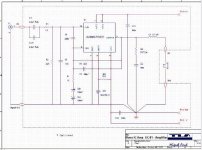
He downloaded some files from a site of which he has forgotten to bookmark and can't find it again. He started to etch the PCB for this LM3886 GC and after completing it, he asked my help to digest the schematics and order the parts for him. On the board there is a capacitor marked C1. In the schematics, there is no such capacitor shown.
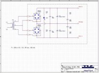
Anyone of you good guys may have experience and knowledge to assist the project to go forward. Presently, it's stalled bcoz of this. I am attaching the board pdf. I hope someone here can assist my friend to continue his project. Thanks.
He downloaded some files from a site of which he has forgotten to bookmark and can't find it again. He started to etch the PCB for this LM3886 GC and after completing it, he asked my help to digest the schematics and order the parts for him. On the board there is a capacitor marked C1. In the schematics, there is no such capacitor shown.
Anyone of you good guys may have experience and knowledge to assist the project to go forward. Presently, it's stalled bcoz of this. I am attaching the board pdf. I hope someone here can assist my friend to continue his project. Thanks.
Attachments
GC help
Cin1 and Cin on the PC board layout are both 2.2uf poly caps and look like Cin1? and C2? on the schemactic. The first two caps after the signal input, these are your coupling caps there to prevent DC from previous stage. Dont understand why useing two in parellel one with a value of 1uf to 4.7uf with the 22K resistor would work fine?????
Cin1 and Cin on the PC board layout are both 2.2uf poly caps and look like Cin1? and C2? on the schemactic. The first two caps after the signal input, these are your coupling caps there to prevent DC from previous stage. Dont understand why useing two in parellel one with a value of 1uf to 4.7uf with the 22K resistor would work fine?????
tiltedhalo, thanks for the reply, but I know nothing about circuit design so cannot comment until the GC gets powered up, if it ever does.
The missing value is the C1 located in the middle of the board where there is a GND next to it, as it doesn't seem to appear in the schematics. Any ideas or suggestions?
The missing value is the C1 located in the middle of the board where there is a GND next to it, as it doesn't seem to appear in the schematics. Any ideas or suggestions?
Thanks dhengk, this seems helpful. I was just going thru the schematics and the pdf and somehow I sense that something is wrong. The pin 2 of the LM3886 seems to be connected to the wrong place on the pdf board, and the schematics seems to be right. Could anyone help verify this?
Thanks.
Thanks.
- Status
- This old topic is closed. If you want to reopen this topic, contact a moderator using the "Report Post" button.
- Home
- Amplifiers
- Chip Amps
- Miguel Font design GC !!! Please help.....