For a while now I have been building chip amps with the usual suspects (LM1875, LM3875, LM3886, OPA549 etc). Quite some time ago I also put together an amp with an LM4780 (A near clone of BrianGT's boards). Anyone who has worked with this chip knows that the pinout is notorious for trying to route one a PCB, the power traces always end up small and ground configurations are typically messy. The other day while surfing I came accross Mark Henessey's page detailing how he P2P'd one of these chips http://www.mhennessy2.f9.co.uk/microamp/index.htm
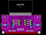
I was inspired with a simple thought that I often don't see implemented here...If the pinout doesn't suit you then change it. Basically what I did was to mount the 4780 like an SMD chip. All of the power supply pins were bent to be on the bottom layer along with the mute pins and the few NC pins thet were already there. Then bent everything else up to the top layer. This allowed a very simple and tidy layout...not to mention very small. The final board is 1" x 2" and is stereo!") I have attached a picture of the eagle board layout. I'll post a picture of the actual amp tonight.
I have attached a picture of the eagle board layout. I'll post a picture of the actual amp tonight.
G.
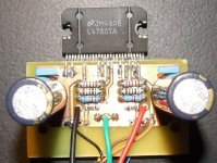
I was inspired with a simple thought that I often don't see implemented here...If the pinout doesn't suit you then change it. Basically what I did was to mount the 4780 like an SMD chip. All of the power supply pins were bent to be on the bottom layer along with the mute pins and the few NC pins thet were already there. Then bent everything else up to the top layer. This allowed a very simple and tidy layout...not to mention very small. The final board is 1" x 2" and is stereo!
I have attached a picture of the eagle board layout. I'll post a picture of the actual amp tonight.G.
Attachments
PierreG said:Very interesting. Can you show the top and botton layers separately?
Sorry I didn't get a chance to post the photo of this board, got distracted with kids/wife and such
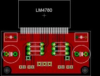
Anyway here is the layout of the top side.
Attachments
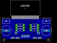
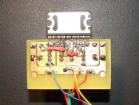
And here is the layout of the bottom side. Note that there is an SMD resistos that goes from the mute pins to ground. The mute pins are tied together just below the pins of the chip. You need to bend a few of the supply pins just a little to give clearance for this trace, or put some kind of insulator over it. Also note that you need to jumper the +VE supply. I didn't add any through hole to do this since it messes up routing on the top layer. It is easy enough to just solder two little pieces of wire to complete the connections. I found that using this layout I get nice big supply traces. Also it can be a bit hard to figure out what pins are on this layer in the picture because I didn't use thermals like on the top. Basically you have the mute pins, all the supply pins and any NC pins that were in the back row on the chip. Look at the datasheet and you will see what I mean.
G.
G.
Attachments
Gcollier said:
Sorry I didn't get a chance to post the photo of this board, got distracted with kids/wife and such
I know what you mean.
Thanks for the PCB
I have been fiddling with routing of this this device and I'm happy to hear I'm not the only one to think it's a pain. The approach shown above is very creative. Like many good ideas, it is "obvious" after someone else has thought of it first. Without going the SMT route, the principal can even be applied somewhat to PTH - there are as couple of adjascent front and rear pin-pairs that would work better if both were either front or back.
Be careful bending the pins -- they can only take so much before breaking. I found this out with a couple of LM3886's that had to be tossed. Think carefgully about what you want to do and then make the bends --once.
Be careful bending the pins -- they can only take so much before breaking. I found this out with a couple of LM3886's that had to be tossed. Think carefgully about what you want to do and then make the bends --once.
Great idea!
Before settling on P2P, I explored similar ideas. Unfortunately, a lack of PCB making facilities stopped me developing the idea, but I like what you've come up with
I nearly used a simple PCB (made using a scalpel) for power, ground and mute, with the audio connections done P2P. But in the end, P2P was easier.
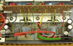
In case you didn't see it, I did a hybrid P2P/homecut PCB in my 4 channel LM4780 amp. This tried to use take best of all approaches, while allowing scope for future mods and experiments - this explains why Veroboard was used for the buffer. Looking at how the signal and power parts of the circuit are separated by 90 degrees, I honestly don't know if I could have made a better layout using a single PCB… Mechanically it works well too - that aluminium bar holds the ICs to the heatsink while supporting the "PCB" and the Veroboard panel, while the design of the chassis is such that the heatsink assembly can be removed after undoing 6 screws
I'm looking forward to seeing how this develops - it looks like a really promising scheme
Mark
Before settling on P2P, I explored similar ideas. Unfortunately, a lack of PCB making facilities stopped me developing the idea, but I like what you've come up with
I nearly used a simple PCB (made using a scalpel) for power, ground and mute, with the audio connections done P2P. But in the end, P2P was easier.
In case you didn't see it, I did a hybrid P2P/homecut PCB in my 4 channel LM4780 amp. This tried to use take best of all approaches, while allowing scope for future mods and experiments - this explains why Veroboard was used for the buffer. Looking at how the signal and power parts of the circuit are separated by 90 degrees, I honestly don't know if I could have made a better layout using a single PCB… Mechanically it works well too - that aluminium bar holds the ICs to the heatsink while supporting the "PCB" and the Veroboard panel, while the design of the chassis is such that the heatsink assembly can be removed after undoing 6 screws
I'm looking forward to seeing how this develops - it looks like a really promising scheme
Mark
Attachments
mhennessy said:Great idea!
Before settling on P2P, I explored similar ideas. Unfortunately, a lack of PCB making facilities stopped me developing the idea, but I like what you've come up with
I nearly used a simple PCB (made using a scalpel) for power, ground and mute, with the audio connections done P2P. But in the end, P2P was easier.
In case you didn't see it, I did a hybrid P2P/homecut PCB in my 4 channel LM4780 amp. This tried to use take best of all approaches, while allowing scope for future mods and experiments - this explains why Veroboard was used for the buffer. Looking at how the signal and power parts of the circuit are separated by 90 degrees, I honestly don't know if I could have made a better layout using a single PCB… Mechanically it works well too - that aluminium bar holds the ICs to the heatsink while supporting the "PCB" and the Veroboard panel, while the design of the chassis is such that the heatsink assembly can be removed after undoing 6 screws
I'm looking forward to seeing how this develops - it looks like a really promising scheme
Mark
Mark,
I'm glad you like it..your design was my inspiration after all

I did in fact see your slick integrated design...VERY nice! Kind of a P2P approach taken to a whole new level! I definately like the use of the angle aluminum. I use a lot it my chassis builds, I have also found that aluminum "T-Track" is great for making small heatsinks or chip hold-downs.
I think my next step will be to add another 0.5" to the height of the board and parallel the two amps by adding the necessary resistors to the board.
If I'm lucky I'll be able to post a photo of the working board.
G.
- Status
- This old topic is closed. If you want to reopen this topic, contact a moderator using the "Report Post" button.
- Home
- Amplifiers
- Chip Amps
- LM4780 Pseudo SMT Design