Well I have done a lot of reading in this forum and I have decided to build my first amplifier. I have decided on a gainclone. I guess the thing that got me onto the trail of these amps was researching the Phoenix speakers on www.linkwitzlab.com and his talking about chip amps. I am an ex-Air Force avionics tech and working on electronics has always been enjoyable to me, I think this will be a fun 'first' amp to build.
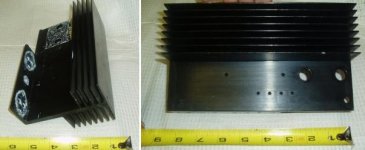
I am on a very tight budget so it may take a while for me get done but I went ahead and bought the first piece of the puzzle a few days ago. I got the heatsink off of eBay and it should be arriving within a few days. I thought the price was fair and it is probably overkill but to me that is usually a good thing. With shipping it was $9.25. From the pics it appears to already have the proper mounting holes for the LM4780 but only time will tell. I have access to only basic tools so that would be a nice bonus.
I plan to use it to drive my modded Optimus LX-5 Pro speakers and will probably also build another to drive my diy T-Line sub. Of course in the long run I plan to build some new speakers and it will be a real challenge for me to pick a design; Phoenix, full-range driver (Fostex), or maybe just some MTM's.
I have not nailed the design down yet but I plan on an unregulated ps and point-to-point construction for the amp (I think I have an idea that may make this both easier to contruct and more durable, I'll see).
I plan to update this thread as work progresses but with an 18-hour load this semester, free time will be a bit of a luxury.
Thanks to everyone for all the great information that is being shared in this forum!
Attachments
Well I finally have the power supply design nailed down (not my own design or anything, just thrown together after sifting through many different designs). I can always modify it later if need be. I will be ordering the parts within a day or two.
All components are from Parts Express:
1ea - Avell 25-0-25 330VA Toroidal Transformer
2ea - 400V 25A Bridge Rectifiers
2ea - Dayton Film & Foil 400V 5% 0.10 uF Capacitors
2ea - Jantzen Metalized Polypropylene 400V 5% 10.0 uF Capacitors
1ea - Power Connector
1ea - 250V 15A DPDT Toggle Switch
1ea - AGC Fuse Holder (2-3A Slow Blo)
16-Guage stranded copper hookup wire
I will also be using 2ea 'Panasonic FC 1500-1800 uF 50V Capacitors' connected directly to the p2p power rails on the LM4780 along with 2ea 'Dayton Film & Foil 400V 5% 0.10 uF Capacitors'. I am still researching these components but they are not a part of the power supply physically although the are electrically. I may also add a few resistors to drain the capacitors during power off situations but I am not convinced that they are needed.
Plugging along...
You can compare with parts of BrianGT LM4780 Kit.
See http://www.chipamp.com/
LM4780 Dual Mono Kit Contents
1 PCB set, consisting of 2 amplifier and 2 rectifier boards.
2 LM4780
6 22 kohm 0.5w compact metal film resistors
4 1 kohm 0.5w compact metal film resistors
4 680 ohm 0.5w compact metal film resistors
2 10 kohm 0.5w compact metal film resistors (mute)
4 0.1 ohm 3w Dale LVR3 power resistors (output)
4 2.7 ohm 2w Panasonic metal film resistors (zobel)
4 0.1 uf BC polypropylene cap (zobel)
4 1500 uF 50v Panasonic FC Capacitors
16 MUR860 On Semiconductor Diodes
4 10 uF Panasonic FC Capacitors
Side note:
I did in fact receive my new heatsink. I prefer the natural aluminum versus a black anodized finish so I removed it with sodium hydroxide. Now the problem is that the person whom I got it from had touched up the bad spots with a permanent marker of some sort. Anyone had this problem and found a solution, or just some ideas to try? It isn't going to make or break the project but it would be nice to remove the marks.
I have tried normal dish soap with brush, hydrochloric acid, and sodium hydroxide; not all at once of course")
Thanks.
I did in fact receive my new heatsink. I prefer the natural aluminum versus a black anodized finish so I removed it with sodium hydroxide. Now the problem is that the person whom I got it from had touched up the bad spots with a permanent marker of some sort. Anyone had this problem and found a solution, or just some ideas to try? It isn't going to make or break the project but it would be nice to remove the marks.
I have tried normal dish soap with brush, hydrochloric acid, and sodium hydroxide; not all at once of course
Thanks.
you can use this tool at Aavid's website to calculate the thermal impedance of the heat sink:
http://www.aavidthermalloy.com/technical/thermal.shtml
unless you are using forced air, put 32 LFM in the box for air velocity.
bookmark that link -- you'll find it very helpful. i think you scored a real bargain with that heat sink.
http://www.aavidthermalloy.com/technical/thermal.shtml
unless you are using forced air, put 32 LFM in the box for air velocity.
bookmark that link -- you'll find it very helpful. i think you scored a real bargain with that heat sink.
lineup, thanks for the link. It has already come in very handy.
Nordic & Hugh M, I will give both of those ideas a try this weekend. Thanks.
jackinnj, wassup in NJ? I lived in Wrightstown (middle of nowhere east of Philly) a long time ago. Your link did come in handy to calculate the heatsinks C/W. Thanks.
Nordic & Hugh M, I will give both of those ideas a try this weekend. Thanks.
jackinnj, wassup in NJ? I lived in Wrightstown (middle of nowhere east of Philly) a long time ago. Your link did come in handy to calculate the heatsinks C/W. Thanks.
duelbox said:
jackinnj, wassup in NJ?
NJ is a political disaster -- corruption is now rivalling Rhode Island -- the state is facing a $4bn deficit and they want to raise our taxes again. I am in Short Hills, about 40 min from NYC btw.
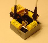
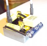
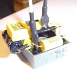
Nothing ever goes as planned. I ran across some transformers on eBay and I just had to buy them. I got 6ea NOS 24VAC/75VA transformers for 23.60, that is shipped by the way. I will use four of them for my amp to give +-24VAC@6A and keep the other two as spares/future project. I think he has 11 of them left so if you want some better jump quick. eBay Item number: 7584210717. I am not affiliated in any way with the person selling these, just giving out the info.
I also have four Panasonic FC 63V 1500uF capacitors on the way too.
Plugging along.
I also have four Panasonic FC 63V 1500uF capacitors on the way too.
Plugging along.
Well sometimes I can be a little slow, it just dawned on me that I now have the perfect opportunity to make a dual mono amplifier. I can use one transformer per rail, per channel (like in other posts in this forum) which would be four transformers total. This also alleviates any concern of the transformers not wanting to play well in parallel. I could then use two LM3886's instead of one LM4780. Since I also ordered 4 Panasonic FC 63V 1500uF capacitors I will have the required two per LM3886. I also like the fact that two LM3886's will be better cooled by my heatsink than a single LM4780 due to the added surface area where the chip(s) contact the heatsink. The only thing that will differ, besides the aforementioned, is the addition of two bridge rectifiers and a few small filter capacitors. I think that is well worth the $30+ in savings for the transformers, plus having four transformers definitely has a 'cool' factor even if there is no tangible benefit (besides going dual-mono).
Comments, advice?
Comments, advice?
Well here is another update. Construction will not actually begin on the power supply for a few weeks but I did get a chance to order a few more goodies today.
Here is what I have ordered.
0.10uF 250VAC X2 safety caps for line-to-line
0.0047uF 250VAC Y2 safety caps for line-to-ground
0.022uF 630VDC foil caps to bypass bridge rectifiers
10.00uF 160VDC electrolytic caps for rail to ground after rectifier
Still need to get rectifiers/switch/power jack/xlr connectors for power out/and other misc.
I have decided to mount the power supply on 3/4" MDF or Birch Ply. Any panel mount devices will be secured using aluminum angle sheet and the rectifiers will be mounted onto flat aluminum sheet. The physical layout is really coming together but of course will not be finished until all parts are obtained. It is actually gonna look quite nice I think. Once I get done with constructing the power supply I will post pics. Then it will be time to focus on the amp itself.
side note: I also ordered 2ea 10-ohm 100-Watt resistors to check all of my transformers before contruction starts.
Well I got to make my Parts Express order today. Rectifiers, XLR connectors, resistors, power switch, power jack, etc are on the way.
I also grabbed 50ft of teflon/silver coated 18AWG wire off of eBay. I know it is only one color but I am used to working on aircraft and all the wiring was the same color... white. Of course they were numbered but with so few wires it won't be a problem. I got the wire, not because it is silver coated, for the teflon coating. That is what I am familiar with and I can attest to the fact that it is much nicer to work with. I hate soldering PVC coated wire to anything that has a a decent amount of mass and end up melting the PVC back a few mm, just annoying to me. I also prefer stripping my wires by hand with a razor blade and teflon coated just works better for me. I guess its just what you are used to. I never thought about the cost of the stuff I worked with when I was in the USAF but now that I have to fork out the cash I wish I were still in, I could save a good bit of money just by using the scraps of wire that we would throw away.
I haven't had a lot of time to just sit down and write a good bit on what is going on with my project, I have to leave in just a bit for class. I just wanted to elaborate a bit on what is going on.
Right now I am concentrating on the power supply and it will be a seperate unit, thanks karma for the hint. Specs are constantly changing but here are the basics.
2 seperate power supplies in one chassis (for dual mono amp)
each power supply consists of:
2 24VAC/75VA split bobbin transformers. Should be around +-35VDC @ 150VA per channnel.
The safety caps are to help with any RF in the mains. I will have a line-to-line cap (.1 uF) at the the power switch and line-to-ground caps (.0047 uF) from the switch to earth. These are the correct caps for this application. X2 rated for line-to-line and Y2 rated for line-to-ground. I will also use the same .1uF caps for line-to-line on the output of each transformer and possibly for the amp itself. Here is a link to some info where I purchased my caps, I cannot find the site where I originally found this info (went much more indepth). http://www.justradios.com/safetytips.html
I am bypassing the diodes in the rectifiers with .022 uF caps. I found this information in several sites but here is one that briefly mentions it http://sound.westhost.com/power-supplies.htm#diodes
I have done a lot of reading in the forums and on the net and I have had a great deal of information to sift through, hence the changing specs. It is 99% nailed down at the moment and I have left room in my layout to allow future mods such as adding more capacitance or adding a snubber circuit.
I want the best linear power supply that I can build, with enough room for future mods and with enough power to allow for future projects since, being a seperate piece, it is modular.
I am sure that I am leaving a lot out, I am in a hurry, but I would like to thank everyone that posts in this forum. All the information, both questions and answers, has helped me immensely with my project.
Thanks again.
duelbox said:
I am bypassing the diodes in the rectifiers with .022 uF caps. I found this information in several sites but here is one that briefly mentions it http://sound.westhost.com/power-supplies.htm#diodes
A diode already has a capacitor in parallel with itself -- the junction capacitance -- this can be 100pF for a MUR860 (@30VDC). If you look at your transformer, diodes, filter caps etc. you will note that you have a tuned circuit which will oscillate at a frequency determined by the leakage inductance of the transformer AND the junction capacitance of the diode -- by putting a diode across the capacitor you just reduce the frequency at which the circuit is resonant !!! If the transformer leakage inductance is high enough you can pull the frequency into the audio domain.
The correct way to null the resonance is with an RC circuit across the diode -- the R and C are functions of the leakage inductance and junction capacitance -- Jim Hagerman has done a very thorough piece on the math at: http://www.hagtech.com/pdf/snubber.pdf
Quite frankly, with a 60 Hz torroid you might not need a snubber but with an EI transformer you most likely will.
jackinnj
Sorry, I did not explain what I am doing, I guess I expect everyone to have ESP (or is that ESPN hehe). My power supply consists of four 75VA transformers and four bridge rectifiers. My plan is simply to make one bridge with no caps across diodes, one with, and one with snubbers. I have not yet worked out values for the snubbers. I will then take these three bridges, of the four, each hooked up to its own transformer and throw them on an o-scope. (I will also connect 1500uF on each rail) I will look under noload conditions and under a 20ohm load which should be about a 60-watts. I plan to hookup two at a time (dual trace) for a general comparision, I am not going to get really technical with my observations. Which ever looks the best will be the design I go with.
I am currently reading the pdf you posted along with this one from Unitrode. I would love to hear some real world values people have used in similar circumstances.
- Status
- This old topic is closed. If you want to reopen this topic, contact a moderator using the "Report Post" button.
- Home
- Amplifiers
- Chip Amps
- Starting my first LM4780 Gainclone amp