I found a few "recycled" transformers locally that are dirt cheap, but won't handle the power I want to put through them. Has anyone used transformers in parallel to get enough juice for an application? I know you can wire transformers in series to double voltages, but I have never seen people use parallel transformers. Thoughts, comments?
I can't think of a good reason this won't work, but I am not an EE, so I figured I would toss out the idea in case others had some insights.
I can't think of a good reason this won't work, but I am not an EE, so I figured I would toss out the idea in case others had some insights.
 ). I think it will be OK, but of course I didn't find that until just after I posted. Don't you love it when that happens!
Re: how?
")
I think I am to the point of dropping a few bucks and trying it out. If it sucks, c'est la vie!
Yea, essentially that is what I found. As long as you accept that there will be losses and that it is not as desirable as a single transformer, and that you need to make sure that the outputs are matched pretty well, then you should be OK. That being said, I have not tried it yet, so we will see.lgreen said:what did you find?
If the transformers don't exactly match up you may have currents flowing in them and extra heat generated.
I think I am to the point of dropping a few bucks and trying it out. If it sucks, c'est la vie!
I am using parallelled transformers for a Class-A amp I'm building. I used four 0.5 ohm 10W resistors, one between each secondary winding and its associated bridge rectifier input so they share the current properly. It works fine, although they are identical transformers they weren't sharing nicely until I added the resistors.
Hey Paul,
Thanks for the tip about using resistors! I never would have thought of that.
I was actually planning to use one bridge rectifier for the transformers, but from what it sounds like, you are using a different bridge for each of your yours. Is there a reason for this?
Thanks again!
Thanks for the tip about using resistors! I never would have thought of that.
I was actually planning to use one bridge rectifier for the transformers, but from what it sounds like, you are using a different bridge for each of your yours. Is there a reason for this?
Thanks again!
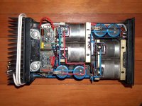
I have done this before but what I found to work the best is to put a bridge rectifier on each transformer and then you parallel the bridge rectifiers. This way you have nothing fighting with each other. I build a 1000Va using two 500VA secondaries with a bridge rectifier on each secondary
have a look at my mosfet amp. here you can see how i did it.
have a look at my mosfet amp. here you can see how i did it.
Attachments
Absolutely! The diodes would prevent slightly mis-matched transformers from feeding into each other!rudi said:I have done this before but what I found to work the best is to put a bridge rectifier on each transformer and then you parallel the bridge rectifiers. This way you have nothing fighting with each other.
That makes 100% sense, but I must admit that rationally didn't even cross my mind until you mentioned it. Thanks!
Oh, and that amp looks great! Extremely clean wiring. I am impressed! My stuff looks like spaghetti most of the time!
rudi said:I have done this before but what I found to work the best is to put a bridge rectifier on each transformer and then you parallel the bridge rectifiers. This way you have nothing fighting with each other. I build a 1000Va using two 500VA secondaries with a bridge rectifier on each secondary
I made 600VA power supply using 3 different transfomers. Voltages was between 33-37V. I put bridge rectifier on each transformer and regulators. Finally I have 3 wires with 29V. Then I parallel them through low resistance power resistors. Same I did on negative side. So total six bridge rectifier and regulators on my GC power supply.
isopannu said:
I made 600VA power supply using 3 different transfomers. Voltages was between 33-37V. I put bridge rectifier on each transformer and regulators. Finally I have 3 wires with 29V. Then I parallel them through low resistance power resistors. Same I did on negative side. So total six bridge rectifier and regulators on my GC power supply.
nice idea.
Quick update: The transformers I was looking at have beecome moot! I just picked two nice 24V CT 12A transformers from the trash and will run them in series in order to get the rails I want for some LM3886's. (See my dumpster dive thread if you want some pics!!) My idea was to tie one end of each transformer to ground and the other ends into a bridge rectifier. Any more comments about that? I know I have to be aware that both stages are in phase so that I don't set up a short circuit, but other than that, are there any suggestions?
I had thought about putting a diode inline before the ground point, but I figured that was asking for trouble since it would set up more of a potential for ground loops (at least if my logic is correct. . . . ).
I had thought about putting a diode inline before the ground point, but I figured that was asking for trouble since it would set up more of a potential for ground loops (at least if my logic is correct. . . . ).
- Status
- This old topic is closed. If you want to reopen this topic, contact a moderator using the "Report Post" button.
- Home
- Amplifiers
- Chip Amps
- Paralleling transformers???