Hello,
I have decided to have a play with a LM3875 and make a gainclone to experiment with.
I have been given a Yamaha AX-730 which has had a repair attempt on it but don't know who tried the repair or what the orig problem was, most of the O/P trannies are missing and other mods done..
Anyway i was thinking about using the transformer from this to experiment with the LM3875. I measured 2x17v ac and 2x46v ac secondaries but have no idea what the amp rating of either is..
I was thinking of using the 17v lines for the amp...
Does anyone have any info on this transgormer...???
Thanks..
David... BD
I don't know anything about that amp, but I would suspect that the 17V rails are a low-current output intended for the preamp. As such, I'm afraid the transformer wouldn't be suitable.
Still, judging by the 46V windings, I bet it's got some impressive heatsinks!
Cheers,
Mark
Still, judging by the 46V windings, I bet it's got some impressive heatsinks!
Cheers,
Mark
Hello,
Thanks for the reply Mark. I will be recycling the heatsinks onto the gainclone, plenty of room on the heatsink for 2 gainclones..") I checked the back of the Amplifier case and it has 600Watts rating for the Amplifier but the heatsinks look a bit too wimpy for that sort of heat dissipation.
I checked the back of the Amplifier case and it has 600Watts rating for the Amplifier but the heatsinks look a bit too wimpy for that sort of heat dissipation.
Maybe they were being a little optomistic or a little loose with their power ratings.
The wire used for the 17v & 46v taps are the same guage so I was hoping that maybe the 17v rails were being used for more than just the preamp.
Does anyone know of a method of testing a transformer for current rating..???
Maybe I should use the transformer and create a bench powersupply so I can regulate it from 0 - 50 volts DC and once I have tested the gainclones and played for a while buy a Transformer for it...
Just musing here....
Have a great day.
Regards,
David... BD
Thanks for the reply Mark. I will be recycling the heatsinks onto the gainclone, plenty of room on the heatsink for 2 gainclones..
I checked the back of the Amplifier case and it has 600Watts rating for the Amplifier but the heatsinks look a bit too wimpy for that sort of heat dissipation.Maybe they were being a little optomistic or a little loose with their power ratings.
The wire used for the 17v & 46v taps are the same guage so I was hoping that maybe the 17v rails were being used for more than just the preamp.
Does anyone know of a method of testing a transformer for current rating..???
Maybe I should use the transformer and create a bench powersupply so I can regulate it from 0 - 50 volts DC and once I have tested the gainclones and played for a while buy a Transformer for it...
Just musing here....
Have a great day.
Regards,
David... BD
More reading, more thoughts.....
I have been reading in this forum and others regarding rewinding Microwave Oven Transformers ( MOTs ) to use in a powersupply. Now I just happen to have some dead microwaves I have been cannibalising for other projects ( a magnetic flux accellerator ) and have some MOTs sitting around...
I might have a play at winding a transformer and see how that goes...
I think I read too much, I get too many ideas... heheheh..
Have a great day..
David... BD
I have been reading in this forum and others regarding rewinding Microwave Oven Transformers ( MOTs ) to use in a powersupply. Now I just happen to have some dead microwaves I have been cannibalising for other projects ( a magnetic flux accellerator ) and have some MOTs sitting around...
I might have a play at winding a transformer and see how that goes...
I think I read too much, I get too many ideas...
heheheh..Have a great day..
David... BD
Hello All...
Ok Transformer update.....
I have decided to use recycle a Microwave Oven Transformer for my Gainclone powersupply during testing. I may purchase another transformer later depending on the sound of this one.
I have removed the secondary ( 2000v ) and wound my own secondary, I decided on +/- 20 Volts center tapped...
If anyone is interested in how I did it let me know and I will give a little info and some photos if needed...
Just need to settle on my gainclone circuit and start putting it together....
Take care..
David.. BD
bezel6 said:I have removed the secondary ( 2000v ) and wound my own secondary, I decided on +/- 20 Volts center tapped...
Wow - that sounds like you put in a lot of effort
Did you have to remove the EI laminations? I have tried this before, and always found it hard to get them all back together again afterwards! Mind you, I haven't tried this since I was a kid...
I'd love to see some pictures if you have them...
Should someone mention electrical safety at this point?

20-0-20 is a good choice - should be good for around 30W per channel
Hello mhennessy,
I have gone to a bit of trouble, but seems to have worked out nicely. Finished winding it tonight.
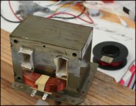
Here is the first pic I didn't dismantle the laminations as they are welded along the sides so would have to grind out the welds to remove the E I Laminations so I cheated by using a hacksaw to cut the end off the 2000v windings ( you can see some marks in the photo which hopefully attached ) I knocked the rest of the coils out with a hammer and lump of wood, I then took some of the insulating material and glued it back into the vacent holes.
I had some enamelled wire, too thin for what I want but good for a test wiring, I calculated I would need 12 loops in the winding to get 10v so tried 12 loops passing through one hole and back through the other, didn't take very long.
Put the multimeter on the ends using alligator clips stood back and plugged in and switched on. I got a touch under 10v so switched off unplugged and wound 1 more loop on, tried again and got 10v exactly. So I would need 26 loops for each 20volt winding.
More to come next post..
PS, I am very careful around mains etc... Worked for a couple years repairing video games, pinball machines and Jukeboxes about 15 years ago... Actually I am thinking about using the Gainclones in a Jukebox I am building....
David... BD
I have gone to a bit of trouble, but seems to have worked out nicely. Finished winding it tonight.
Here is the first pic I didn't dismantle the laminations as they are welded along the sides so would have to grind out the welds to remove the E I Laminations so I cheated by using a hacksaw to cut the end off the 2000v windings ( you can see some marks in the photo which hopefully attached ) I knocked the rest of the coils out with a hammer and lump of wood, I then took some of the insulating material and glued it back into the vacent holes.
I had some enamelled wire, too thin for what I want but good for a test wiring, I calculated I would need 12 loops in the winding to get 10v so tried 12 loops passing through one hole and back through the other, didn't take very long.
Put the multimeter on the ends using alligator clips stood back and plugged in and switched on. I got a touch under 10v so switched off unplugged and wound 1 more loop on, tried again and got 10v exactly. So I would need 26 loops for each 20volt winding.
More to come next post..
PS, I am very careful around mains etc... Worked for a couple years repairing video games, pinball machines and Jukeboxes about 15 years ago... Actually I am thinking about using the Gainclones in a Jukebox I am building....
David... BD
Attachments
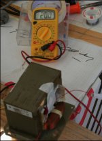
Next I unwound the 13 loops and measured some .8mm enamelled wire twice the length of the .5mm.
I then passed this wire through the holes to give 26 loops, not this took a while.. I superglued the coils in, stripped the ends put on multimeter and tried again, as you can see in attached photo I have 20v ac....
Pic of other side in next message...
David.... BD
I then passed this wire through the holes to give 26 loops, not this took a while.. I superglued the coils in, stripped the ends put on multimeter and tried again, as you can see in attached photo I have 20v ac....
Pic of other side in next message...
David.... BD
Attachments
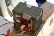
Here is the pic of other side...
That was the last pic I took so far, needed more wire for the second winding so bought some more tonight and did the second winding, took measurements and got 20v from both windings and when I join the center 2 together got 40v on the ends...
Took a little while but very happy with the results and should be good for testing.
Most of my first gainclone will be from recycled parts or stuff I have around here..
I started putting my Gain together tonight, I usually prefer using PCB's but decided to try P2P...
Will take some more photos as I go so if people want to see how things are progressing I'll keep posting...
Catch ya..
David.... BD
Attachments
You've made that look very easy. That's a big transformer - plenty of VA available from that. Have you measured how much current you can draw from the windings before they fall by 10% (a good rule of thumb)?
You might consider keeping the two windings seperate, and having seperate bridges for each. I prefer to do this with power amps because it makes managing earths a bit easier - keeps charging currents away from the star point.
I like the jukebox gainclone idea too
Cheers,
Mark
You might consider keeping the two windings seperate, and having seperate bridges for each. I prefer to do this with power amps because it makes managing earths a bit easier - keeps charging currents away from the star point.
I like the jukebox gainclone idea too
Cheers,
Mark
The transformer in its previous life was about 900va so no problems with the primary winding.
There is plenty of room to add some more windings later if I want so may put in some more once I have the Amp working and up the voltage a bit by wiring the new windings in series with the current 2 windings.
Yes my plan is to use 2 bridges, I have 2 powersupplies here at the moment I will cannablise for the bridges, both powersupplies are rated as 400w so the bridges should be able to handle 1 rail of the clone each.
I have not measured the current I can draw, will calculate it one day if I think I need to pull high currents through the windings.
Re: Nordic... Building a Jukebox is easy, it is similar to carving an elephant out of marble....
You get the material and tools, in the carving example you stand next to the marble with hammer and chisel in hand and chip away anything that doesn't look like an elephant...
I have been taking some pix of the Jukebox as I go as a friend wants to make one too and wants me to send him info. If I get time and people are interested I may put up some info about the making of a Juke ( which BTW is for my wedding in less than 3 weeks time ).. There is a lot of info around the web about this subject so do some searching if you want inspiration now....
Have a great day..
David... BD
Hello Nordic,
A bit off topic but anyway... I have a Celeron 556Mhz running XP bare minimum install a reasonable soundcard can't remember which one but may change it out for my sound blaster live later and using SKJukebox for the software. I have mapped out the matrix to a keyboard controller so I will be removing the controller and cable from a keyboard and using about 14 keys to control everything. These will eventually be mounted to the right of the 15 inch monitor I use for display..
I currently have the output from the soundcard going to an old Realistic Receiver/Amp I bought when I was about 15, I am 42 now, that is going out to a couple of 25 year old passive 2 way crossovers which then drive 2x25 year old 12inch full range speakers and 2 new tweeters. The crossovers and 12 inch drivers have never been used, I bought them a quarter century ago to build some speakers but then bought a house, got married for the first time had a little girl and never got around to using them just carted them around with me.
I have had it all hooked up for New Years Eve and it sounded nice, loud and fairly clean..
What I want to do is now build an active crossover and use maybe 4 to 6 gainclones to drive the speakers directly.... Or maybe some other Amp Modules for base and gainclones for higher frequencies.. But this will have to wait till after I am married...
I would like to use 2 gainclones instead of the Realistic Amp for the wedding if possible but have a lot of work to do on the cabinet yet so may not get them in before hand...
Oh I got my MOTclone going tonight, hooked it up to a single 8 inch speaker for testing and seems to work ok, needed to keep the volume down as the neighbours were in bed and the jukebox is in the carport which is what I tested it on, will have to wait till the weekend before I can use some decent speakers to see how it sounds..
I better get to bed, the wife to be is not too happy with me spending most of my time in the garage lately while we are still getting the wedding organising done...
Have a great day/night...
Catch ya..
David.... BD
Hello All...
An Update... I have been very happy with the sound and output of my first gainclone. So decided to make it stereo ( or 2 monoblocs ) and purchased another LM3875T plus a couple caps to make it..
Got a bit of fibreglass board with lots of holes in but no copper tracks to help with mounting as I wanted to do some changing of components for experimenting after it was completed...
Anyway i learned a valuable lesson after putting it all together, NEVER RUSH TO FINISH.. I was working outside and it was getting dark so I rushed a bit, got the amp together plugged it in and turned on with no input or speakers, volt offset measured ok ( about the same as the other chip when first completed ) so turned off hooked up to Jukebox source and hooked up a speaker hit the on switch and BANG........

I swore a couple times turned it all off and went to bed... I had a look yesterday morning and found a big hole in the front of the LM3875. I also worked out why it went belly up... The insulating disk I had on the screw had fallen off as I was trying to attach to the heatsink and I didn't notice it in the dark... Oh well live and learn...
Will buy a new chip tonight on my way home and maybe take a photo of dead chip before dismantling...
Have a great day....
David.... BD
An Update... I have been very happy with the sound and output of my first gainclone. So decided to make it stereo ( or 2 monoblocs ) and purchased another LM3875T plus a couple caps to make it..
Got a bit of fibreglass board with lots of holes in but no copper tracks to help with mounting as I wanted to do some changing of components for experimenting after it was completed...
Anyway i learned a valuable lesson after putting it all together, NEVER RUSH TO FINISH.. I was working outside and it was getting dark so I rushed a bit, got the amp together plugged it in and turned on with no input or speakers, volt offset measured ok ( about the same as the other chip when first completed ) so turned off hooked up to Jukebox source and hooked up a speaker hit the on switch and BANG........
I swore a couple times turned it all off and went to bed... I had a look yesterday morning and found a big hole in the front of the LM3875. I also worked out why it went belly up... The insulating disk I had on the screw had fallen off as I was trying to attach to the heatsink and I didn't notice it in the dark... Oh well live and learn...
Will buy a new chip tonight on my way home and maybe take a photo of dead chip before dismantling...
Have a great day....
David.... BD
- Status
- This old topic is closed. If you want to reopen this topic, contact a moderator using the "Report Post" button.
- Home
- Amplifiers
- Chip Amps
- First Gainclone. AX-730 Transformer Question.