Everyone of you designing pcb's for opamps knows, how bad the layout of the single opamp is, concerning ground tracing between the bypass caps.
It's always a dilemma to create short and large traces between the bypass caps. Double sided is not a perfect solution, still some limitations for this current path.
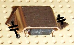
So, tonight I had the idea to attach some kind of cupper cap on top of the chip, offering a good ground trace.
What do you think, would this have the disadvantage to add some parasitic capacitance to the other pins?
Here the first try, to illustrate the idea. It would have the advantage to act as little heathsink and therefore stabilizing the amp.
Franz
It's always a dilemma to create short and large traces between the bypass caps. Double sided is not a perfect solution, still some limitations for this current path.
So, tonight I had the idea to attach some kind of cupper cap on top of the chip, offering a good ground trace.
What do you think, would this have the disadvantage to add some parasitic capacitance to the other pins?
Here the first try, to illustrate the idea. It would have the advantage to act as little heathsink and therefore stabilizing the amp.
Franz
Attachments
No bearing on your concept other than finetuneing, I have seen pictures of the charge buildup on the plates in those glass lab capacitors (lyden jar?) anyway, what stuck with me is that the patern seemed to radiate more from sharp edges, and basicaly only radiates on edges overall, so maybe you want to sand the edges down some... come on, I know you like playing with your metal tools, i just discovered my grandads metal working tools this weekend, he had 3 lathes at home when I was little.
Only advantage I see is the "cage" you create with your grounded cap.
Good against HF radiation.
And of course the extra cooling.
As to grounding I´d think that a "short as possible" lead below the IC (or ground layer) would have less inductance.
(especially with the bents in the copper sheet).
Then again we´re talking audio so that doesn´t matter as much as in digital circuitry for example.
Of course you´d still have to sort out grounding anyway as the opamp wouldn´t be your only element in the circuit?
greets & happy christmas days
Jens
Franz, I think you should analyze your situation a bit more. What was the problem? I think you enviromnent is pretty good if you have a groundplane and a normal doublesided board. One way to make things better is to use SMD parts with will be tighter to the board and are also smaller with means better chance of good decoupling.
1 sqcm on a pcb => 3 pF
1 sqcm on a pcb => 3 pF
i just say thin PTFE double sided PCB-material, its good enough for microwaves so i guess it will be ok for audio as well 
Seriously speaking, shielding is good so there is nothing wrong with an "IC-cap" made of copper but i dont think it is necessary, not even with highspeed opamps..
If you want a short path to ground, use SMD capacitors and place them underneath a DIP opamp and plate through to the groundplane side of the PCB.
Yes it is compared to a singlesided board.Franz G said:Double sided is not a perfect solution,

Franz G said:It's always a dilemma to create short and large traces between the bypass caps. Double sided is not a perfect solution, still some limitations for this current path.
So, tonight I had the idea to attach some kind of cupper cap on top of the chip, offering a good ground trace.
What do you think, would this have the disadvantage to add some parasitic capacitance to the other pins?
Yes, you are capacitive coupling the signal pins.
Franz, how hard can it be?
Simple.
Single layer, of course.
Attachments
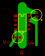
peranders said:Easy if it won't draw any traces under the opamp....
Do you find it hard to put a feedback resistor there?
An SMD resistor can be put there easily, and the ground trace can be a little thinner.
Also, smaller bypass caps (SMD if you want) can easily be placed right after the electrolythics.
This layout is very good for modern, fast, wide bandwidth op-amps.
I don't understand the need for double layer, when there is no need. It may be good only as a show-off.

Also, return the currents to a central point (a star ground) instead of undeliberately using a ground plane for that, which should only serve for shielding, connected to one ground point on the circuit.
- Status
- This old topic is closed. If you want to reopen this topic, contact a moderator using the "Report Post" button.
- Home
- Amplifiers
- Chip Amps
- Grounding Idea for single opamps