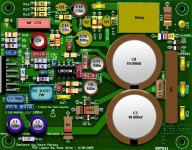
hi!!! i've made the REV1 and cant find out what is wrong. I'm getting -V at output.
i measured the +v,-v, GND of LM3886 and +v, -v of lm318 and the values are OK.
anyone else had this problem?
here some pics:
(i know it's ugly, it's just a test).
i measured the +v,-v, GND of LM3886 and +v, -v of lm318 and the values are OK.
anyone else had this problem?
here some pics:
(i know it's ugly, it's just a test).
An externally hosted image should be here but it was not working when we last tested it.
An externally hosted image should be here but it was not working when we last tested it.
An externally hosted image should be here but it was not working when we last tested it.
peranders said:How about the MUTE pin? Connected to anything? No inputs are floating (unconnected)?
MUTE is connected to -V trough a 33K resistor.
mmm i think that there is no input floating, but i will double-check. what is strange to me is that both channels are doing the same think, -V at output.
thanks
Jorge.
BrianDonegan said:My best guesses are:
- A component mounted between the wrong two holes (on both sides)
- A solder bridge jumping tracks (hard to see in pic, but there are several very close tracks on the layout)
- Fried 3886s (less likely I suppose, but possible)
i will check as soon as i can. the first option sounds possible. the first, i checked for jumping tracks, and the third, fried 3886, its possible but they were brand new.
thanks!

I have accidently put components between the wrong holes before. I usually print out the component locations, then draw them in by hand before mounting components now (or use toner transfer and print then right in the board). I kind of like the look of the hand-drawn components though.
BrianDonegan said:I have accidently put components between the wrong holes before. I usually print out the component locations, then draw them in by hand before mounting components now (or use toner transfer and print then right in the board). I kind of like the look of the hand-drawn components though.
great idea, i will start doing it!!! i mean to hand-write the component layout.
Same problem?
http://www.diyaudio.com/forums/showthread.php?postid=795197#post795197
He had full mains voltage on the outputs of both channels, turned out to be a couple reversed caps.
http://www.diyaudio.com/forums/showthread.php?postid=795197#post795197
He had full mains voltage on the outputs of both channels, turned out to be a couple reversed caps.
Re: Same problem?
thanks!! i asked him what caps were reversed.
BrianDonegan said:http://www.diyaudio.com/forums/showthread.php?postid=795197#post795197
He had full mains voltage on the outputs of both channels, turned out to be a couple reversed caps.
thanks!! i asked him what caps were reversed.

- Status
- This old topic is closed. If you want to reopen this topic, contact a moderator using the "Report Post" button.
- Home
- Amplifiers
- Chip Amps
- cant make it work: mauro penasa rev 1