Hi Ron
the only additional part is the extra bypass caps 100nf. there is alot of them. then the 4 x main caps. nowadays these are cheap. i prefer the Sprague seeing that are very good quality. then there is the 16 xMUR860
now i know that the original recommendation is Multilayer ceramics. but i have used polystyrene, and it does not sound as choked as the Multilayers. (and that is just my experience) I am not aware of any other ill effects. but there could be such issues but i have not experienced them
just another thought. the board should measure 175mm x 150 mm when printed.
this is two stereo boards. you can chop in half if you like once you etched them or just use the two guide lines as indicated
Mauro recommends that you keep the 12V , so go for that with 1k resistors
Cheers
Thank you very much. Will do. What are the parts marked as "Bridge"? Are those just low resistance jumpers, as in the original Rev.C?
- Ron
P.S. Carlos, where can I go to learn all about the snubbers you recommend. I admittedly know nothing about them and am interested in how they work. Thanks!
- Ron
P.S. Carlos, where can I go to learn all about the snubbers you recommend. I admittedly know nothing about them and am interested in how they work. Thanks!
ron.eddy said:Thank you very much. Will do. What are the parts marked as "Bridge"? Are those just low resistance jumpers, as in the original Rev.C?
- Ron
correct you get 0 Ohm "resitors" and it looks much neater. please take notice of the two jumber under the input cap and under the relay
ron.eddy said:P.S. Carlos, where can I go to learn all about the snubbers you recommend. I admittedly know nothing about them and am interested in how they work. Thanks!
Search this forum.

Let's be constructive
I can't be quiet.
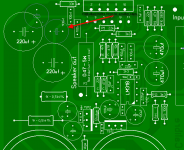
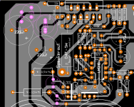
Rudi, there's a lot of space around those 220uF caps, so why not position them as close as possible to the LM3886, and with similar distances?
You can relocate that 1k resistor easily by rotating it by 90º and moving it a little to the right.
One thing I also don't like is the position of those 100uF electrolythics around the LM318 op-amp, but that means a lot of work to make there.
rudi said:and here is the component side.
I can't be quiet.
Rudi, there's a lot of space around those 220uF caps, so why not position them as close as possible to the LM3886, and with similar distances?
You can relocate that 1k resistor easily by rotating it by 90º and moving it a little to the right.
One thing I also don't like is the position of those 100uF electrolythics around the LM318 op-amp, but that means a lot of work to make there.
Attachments
Hi Carlos
something like this. this means i will have to redo my boards well that is not really a problem
I moved the 100nf for negative to pin 4 and implemented a ground through the middle of the LM318
I will have to get some low profile low ESR caps because i like to clamp the chip to the heatsink
something like this. this means i will have to redo my boards
well that is not really a problemI moved the 100nf for negative to pin 4 and implemented a ground through the middle of the LM318
I will have to get some low profile low ESR caps because i like to clamp the chip to the heatsink
Attachments
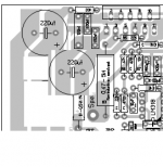
Ok this is as optimised as I can get it. there is space for some small caps closer to the chip and my two larger caps are also indicated.
I always allow for a clamp mounting method for the LM3886 so i had to move the components away a bit. this method also allows for additional cooling
I always allow for a clamp mounting method for the LM3886 so i had to move the components away a bit. this method also allows for additional cooling
Attachments
rudi said:Hi Carlos
something like this. this means i will have to redo my boards
Yes, Rudi, that's much better.
I prefer this arrangement to the one you have on the next post, btw.
rudi said:I moved the 100nf for negative to pin 4 and implemented a ground through the middle of the LM318
That's the way to do it.
Now move the 100uF cap (C11) to pin 4 too.
I know, that means some changes there.
Sorry to give you so much work.

Rudi-
you might have more flexibility if you use a smaller diameter for youe 220uF caps. We are using 50V caps there that are only 10mm and can get them much tighter to the 3886 chip. Also, the 5mm Wimas for the 100nF allow good access to the chip. You can also add another 100nF across the rails.
you might have more flexibility if you use a smaller diameter for youe 220uF caps. We are using 50V caps there that are only 10mm and can get them much tighter to the 3886 chip. Also, the 5mm Wimas for the 100nF allow good access to the chip. You can also add another 100nF across the rails.
Carlos, do you think I am Houdini  well I see what i can do
Brian i will fit some smaller ones. i did allow for 13mm cappies. i tried the one accross the rails but i prefer it without. I know it sounds strange but on recommendation from Mauro i removed as much bypass caps (also on the diodes). and HEY it sounds better. but apparently this is ONLY the case with very fast diodes, so please do not remove just because i found a difference (by the way it was more open and also a beeper soundstage)
I am only indicating what is needed, and allowing space for the rest. and also keeping my personal needs in consideration,
so what is the verdict. shall we stop the design once i have managed to fit the 100uf onto pin 4
anybody that wants to build the amp a"s is" please go ahead. it really is stable now and i can't get it to clip untill i have reached 56W and believe me it is LOAD in my system is probably the full 68W but i still need to test that. so that is still on my to do list
there is a couple of other test that Mauro recommended and i will be doing them soon.
well I see what i can do Brian i will fit some smaller ones. i did allow for 13mm cappies. i tried the one accross the rails but i prefer it without. I know it sounds strange but on recommendation from Mauro i removed as much bypass caps (also on the diodes). and HEY
it sounds better. but apparently this is ONLY the case with very fast diodes, so please do not remove just because i found a difference (by the way it was more open and also a beeper soundstage)I am only indicating what is needed, and allowing space for the rest. and also keeping my personal needs in consideration,
so what is the verdict. shall we stop the design once i have managed to fit the 100uf onto pin 4
anybody that wants to build the amp a"s is" please go ahead. it really is stable now and i can't get it to clip untill i have reached 56W and believe me it is LOAD in my system is probably the full 68W but i still need to test that. so that is still on my to do list
there is a couple of other test that Mauro recommended and i will be doing them soon.
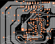
just decided. we are NOT going for the pin 4 option. it makes all other tracks to long . if somebody feels that by having the 100uf at pin 4 I have found a great deal of real estate under the board that is not used
so any other ideas before i go and enjoy my holiday and the hot sun outside
so any other ideas before i go and enjoy my holiday
and the hot sun outside rudi said:I know it sounds strange but on recommendation from Mauro i removed as much bypass caps (also on the diodes). and HEY
I agree, I didn't notice you had those caps across the diodes.
Let them be as optional if you want, but just don't use them.
rudi said:just decided. we are NOT going for the pin 4 option. it makes all other tracks to long . if somebody feels that by having the 100uf at pin 4 I have found a great deal of real estate under the board that is not used
Yes, it makes the other tracks longes, specially the feeback loop, which should be kept as small as possible.
I would use the 100uF cap under the board, near pin4, and leave it's original position empty.
rudi said:Carlos, which one do you prefer. the first post or the second. one. on the second i have all the tracks as short as possible and the reg's are also much closer. the neatness factor did suffer a bit.
I prefer the position and orientation of the 220uF caps near the LM3886 on the first post.
And btw as you are using 1k resistors before the regs (the same value as for the zeners, no?), why not take advantage of that and use a bigger cap just before the regs? Can you fit something around 100uF?
You are making an RC filter there.
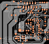
I have changed the layout slightly. i have included space for almost all size caps next to the LM3886 and also the option to have a RC filter on the LM318 power supply (it might, it might not work for you....but it is there for you to try) I think I'll finalize the board unless there is any other suggestions and give you all the final PDF
Attachments
rudi said:I have changed the layout slightly. i have included space for almost all size caps next to the LM3886 and also the option to have a RC filter on the LM318 power supply...
Well yes, it's better now.
Just a side note for those who will build this amp, fill the holes of the unused caps with solder.
You can go on holidays now, Rudi.
- Status
- This old topic is closed. If you want to reopen this topic, contact a moderator using the "Report Post" button.
- Home
- Amplifiers
- Chip Amps
- X-Calibre : Hot Rodding Mauro Penasa's LM3886 design