OK!!! 
Tested one chip tonight. i soldered a 20uF feedback cap on one chip. Before cap it measured 43mV dc offset. With the cap.... 0mV
Ok, my measuring equipment can only handle down to mV but im still really happy!!
Thanks a million for ALL help!!!
will report when its finished.
Best regards
Nicks
Tested one chip tonight. i soldered a 20uF feedback cap on one chip. Before cap it measured 43mV dc offset. With the cap.... 0mV
Ok, my measuring equipment can only handle down to mV but im still really happy!!
Thanks a million for ALL help!!!
will report when its finished.
Best regards
Nicks
Ok, update...
Things are not going my way...
I hooked up three 3886 in parallell. Each individually doesnt produce any dc that i can measure. i.e its below millivolt.
But when i connect them in parallell without signal they produce 25 mV together and get REALLY . They get so hot within 5-6 seconds. now if i hook them up separately i have no problem whatsoever. they dont get hot at all... and no DC...
Ok, when i connect them to my bridge circuit (still no input signal) they give me about 160mV and get really
I measured the dc coming from the bridge circuit and its 3mV and 5mV on the both outputs.
Now can someone please tell me why the chips gets SO ??
And why i get 160mV DC when it in theory only should be the gain of 3886 (20) times 3 or 5???
Best regards
Nicks
Edit: I disconnected all chips again and ran them individually. Still no DC offset from them. Then i connected 2 of them in parallell. And no DC. No heat. When i connected the third i got dc and a small humming sound and i measured 0,585 v ac. So i think i need to resolder the third chip and see if it works.
I could still need some ideas of where it went wrong...
Things are not going my way...
I hooked up three 3886 in parallell. Each individually doesnt produce any dc that i can measure. i.e its below millivolt.
But when i connect them in parallell without signal they produce 25 mV together and get REALLY
. They get so hot within 5-6 seconds. now if i hook them up separately i have no problem whatsoever. they dont get hot at all... and no DC...Ok, when i connect them to my bridge circuit (still no input signal) they give me about 160mV and get really
I measured the dc coming from the bridge circuit and its 3mV and 5mV on the both outputs.
Now can someone please tell me why the chips gets SO
??And why i get 160mV DC when it in theory only should be the gain of 3886 (20) times 3 or 5???
Best regards
Nicks
Edit: I disconnected all chips again and ran them individually. Still no DC offset from them. Then i connected 2 of them in parallell. And no DC. No heat. When i connected the third i got dc and a small humming sound and i measured 0,585 v ac. So i think i need to resolder the third chip and see if it works.
I could still need some ideas of where it went wrong...
It flows current into both inputs of the LM3886. This creates voltage drops. I'll guess you have the input DC connected? If yes you have a non controlled environment. Have you read the AN-1192 and understood how you should do to minimize the offset? Notice that it's hard to get it working real good if you don't have any offset trim AND the input DC connected.
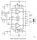
When you connect them in parallell
you should use small output resistors.
See the parallell schematic of LM4780, below.
LM4780 is basically 2 LM3886 in one chip.
But 2 separate LM3886 chips has better cooling.
Outputs are joined together using 0.1 Ohm resistors.
If you already use output resistors, I do not know how to advice you.
Also does this schematic show
each amplifier having its zobel filter. C+R from output to ground.
Attachments
DC offset
I imagine the bridgeing adapter is unity gain inverting and non-inverting buffer? If it is check the specs on the op amps used some can produce a fair amount of offset, 3 to 5 MV is edgy.
Like peranders said, I think you have circiut inequality causeing current to flow. Your output current shareing resistors should be .1 to .15 ohm 1% 3w to 5w units it is imparitive to use 1% units, matching provides ballanced equality on the outputs. If you are useing 5% resistors current missmatches up to the tolerance can result. Also check your grounds I always try to flood fill a ground plane! Just the differance off .1 ohms can cause problems.
Thanks for the help guys. All resistors are matched within 0,1% even the output resistors. They are two 0,22ohm, 5w in parallell for some safety.
I use this bridging device : http://sound.westhost.com/project14.htm
However i havent put in the input capacitor according to AN 1192. But i will do so and post the results of course!
BIIIIG thanx to all for helping me!!
I use this bridging device : http://sound.westhost.com/project14.htm
However i havent put in the input capacitor according to AN 1192. But i will do so and post the results of course!
BIIIIG thanx to all for helping me!!
Just because it bothers me a lot that things arent working, i went and measured the gain resistors again.
Chip 1 has 0,995k and 20,41k gives gain of 20,5126.
Chip 2 has 0,995k and 20,39k gives gain of 20,4926
Chip 3 has 0,995k and 20,40k gives gain of 20,5025
The extremes (chip 1 and 2) differ 1,0009 or 0,01%
This should be ok i guess...
Chip 1 has 0,995k and 20,41k gives gain of 20,5126.
Chip 2 has 0,995k and 20,39k gives gain of 20,4926
Chip 3 has 0,995k and 20,40k gives gain of 20,5025
The extremes (chip 1 and 2) differ 1,0009 or 0,01%
This should be ok i guess...
- Status
- This old topic is closed. If you want to reopen this topic, contact a moderator using the "Report Post" button.
- Home
- Amplifiers
- Chip Amps
- DC offset question