ok, so ive been testing different psu's to find out which is the better one i tried a ct trafo with 1 10000uF on each rail and a snubber(res+101cap)with that. sounded great then i took off the snubbers and it still sounded ok. then i tried something different. i put one of the 10000uF caps +side to +rail, and -side to -rail, but i kept the snubbers going from each rail to ground. each of these psus were tested on a opa541 noninverting amp. this sounded better than all the others it sounded like it had more "punch" and clearer sound and also, sounded more detailed.
just thought i would put this out there so people could think about it
P.S. the opa541 was bypassed with 2 220uF nichicon caps
just thought i would put this out there so people could think about it
P.S. the opa541 was bypassed with 2 220uF nichicon caps
Im a little confusedthen i tried something different. i put one of the 10000uF caps +side to +rail, and -side to -rail,
 are the caps connected as they are normally?
but i kept the snubbers going from each rail to ground. each of these psus were tested on a opa541 noninverting amp. this sounded better than all the others it sounded like it had more "punch" and clearer sound and also, sounded more detailed.
Where the snubbers kept unconnected?
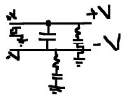
-----------+CAP---------V-
-----------GND----------
------------CAP(-)-------V+
the positive terminal of the 10000uF cap is connected to V+
the negative terminal of the cap is at V-
the snubbers still go from each rail to ground
so there is only 1 10000uF cap going from positive rail to negative rail(no connection to ground)
this was used on opa541 and sounded better than all other configs (IMO)
just thot i would put this out there so people could try it and see if they like it as much as i do.
another thing when there are 2 10000uF caps (going from each rail to ground) there is only 5000uF of capacitance between the rails because it divides the capacitance like putting resistors in parallel. this way you can use only 1 capacitor and get twice the capacitance. IMO this sounded more controlled and detailed and just better than the others.

I think I remember Nelson Pass commenting about doing this, but if memory serves me correctly, he also suggested using caps that were rated at 4X the rail voltage. 
After a half hour of searching I found a somewhat relevant post.
http://www.diyaudio.com/forums/showthread.php?postid=516431#post516431
Maybe I confused 4X capacitance with the required voltage rating. Looking at the power supply schematic, they are using 120V rails and 250V caps. So maybe it's twice the rail voltage. Hopefully someone more knowledgeable than me can chime in. But my point is that you might be exceeding the voltage rating of your capacitors.
I remember there being a thread about this on gainclone.com, but I can't seem to find it.
I think the deciding factor in whether or not this type of capacitor arrangement is good for gainclones is the ground current. Anybody know if there is a significant ground current in gainclones?
edit:
Jaudio, I think it's like this:
----------------(+ cap)----------------- (+ rail)
------------------------------------------ ground
----------------(- cap)------------------ (- rail)
no there is only one cap
the cap has to have a rating of both rails added together at least
so if u have +-30V rails u have to have a cap with at least 60V rating.
my rails are +-15VDC and my 10000uF cap is rated at 50VDC
P.S. sorry for the bad schematic but i wanted to make it quick
the cap has to have a rating of both rails added together at least
so if u have +-30V rails u have to have a cap with at least 60V rating.
my rails are +-15VDC and my 10000uF cap is rated at 50VDC
P.S. sorry for the bad schematic but i wanted to make it quick
Attachments
Nordic said:I was going over the circuit for my old sansui amp totay and was amazed by how it seems to draw on a bit of everyone's input here... even a small snubber...
Just curious: where do you see a 'small snubber' there?
Also, what does this schematic has to do with what's being discussed here?
- Status
- This old topic is closed. If you want to reopen this topic, contact a moderator using the "Report Post" button.
- Home
- Amplifiers
- Chip Amps
- psu's