Happy Thanksgiving,
This is a quick report of power output with the LM4780 Kit used in parallel mode. Using the kit and rectifier capacitance(which I think is only 1500uf) used, I was only able to generate 81W into 4ohms and 50W into 8ohms, before the output clipped. I expected something closer to 120W into 4 ohms per app notes. I increased the capacitance to 2x8200 per rail and was able to generate 65W into 8 and 116W into 4, before the output clipped - much more in line with the app notes.
-BG
It would be also useful to specify transformer being used.
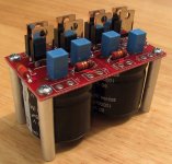
That's also one reason that PS boards feature now space for larger capacitors. If somebody wants more measured power (especially in parallel mode) upgrading is easy.
Supplied 1500u caps represent the best compromise between price of the kit, desired sound signature, convenience of packaging and shipping costs.
Attachments
capacitance has nothing to do with the power -- it's rail voltage, amplification factor and HEATSINKING !!!!
if you don't heat sink these chips properly they go into thermal protection mode -- for both my parallel and bridged boards I use a pair of heat sinks fashioned into a tunnel and drive them with about 100cfm of air.
here's what the power bandwidth should look like in parallel mode:
if you don't heat sink these chips properly they go into thermal protection mode -- for both my parallel and bridged boards I use a pair of heat sinks fashioned into a tunnel and drive them with about 100cfm of air.
here's what the power bandwidth should look like in parallel mode:
An externally hosted image should be here but it was not working when we last tested it.
jackinnj said:capacitance has nothing to do with the power -- it's rail voltage, amplification factor and HEATSINKING !!!!
That's right.
But one thing ends in another, and higher capacitance also means more stable PSU voltage.
Peter, thanks for that and I can appreciate what you guys have put together. By the looks of your pic, that would offer the capabilty I was looking for. As far as the transformer goes, I am using an 800VA, right now for only 2CH. This is a prototype and my first amp and my plan was, once I got a handle on the grounding (not quite there yet, but moved the load rtn off the amp board to the PS and ran a single wire from the PS to the amp boards and things got quite a bit better) and got a better feel for how much of a heat sink I would need, I would then expand this to 6CH.
jackinnj, I think you are being a little closed minded (see Carlosfm). I am not exactly sure what your objection was to as all I did was report measurements. What do you think maintains your rail voltage, anyway? If you don't believe me, why don't you drop your PS caps to, say, 100uF, then see what kind of power you can pump out of your parallel mode amp without clipping the output. Just about any heat sink would do for this test as it only takes less than a minute to make it -- no protection mode. I plan on working the heat issue at a later time.
-BG
rgrayton said:
jackinnj, I think you are being a little closed minded (see Carlosfm). I am not exactly sure what your objection was to as all I did was report measurements. What do you think maintains your rail voltage, anyway? If you don't believe me, why don't you drop your PS caps to, say, 100uF, then see what kind of power you can pump out of your parallel mode amp without clipping the output. Just about any heat sink would do for this test as it only takes less than a minute to make it -- no protection mode. I plan on working the heat issue at a later time.
-BG
i am always closed-minded.
the capacitor determines two things -- (1) the ripple voltage and 2) ability to respond to instantaneous change in current demand. so you run the math and figure out what you can get away with as a minimum capacitor value. you can then caclulate the optimal value making some guess as to the period of the peak, and the instantaneous current demand and run the math.
still has little to do with the amount of power once equation 1 is solved.
figure this -- if you were running the amp with a 80kHz switching supply you could get away with a 330uF capacitor and still achieve the power and THD stats which National points out. and 330uF would probably be overkill.
the heat sink issue is a real world-critical one if you want to squeeze the last oink out of the pig. put an a.c. ammeter on the power supply input line and you'll how much energy is to be dissipated through the heat sink at idle. hopefully most of the rest of the energy is going into your load when you crank it up. you can determine the thermal impedance from National Semi's excel spreadsheet here:
http://www.national.com/appinfo/audio/files/Overture_Design_Guide15.xls
you can then go to the Aavid/Thermalloy website and use their java applet to calculate the dimensions of the heat sink. don't forget that "free" air moves at about 32 cfm.
i've run bridged and paralleled amps for hours at their maximum stated output power -- but I use a heat sinks with a È/W of 1.0 to 0.8 AND a small computer fan. national goes out of their way to point this out on their website. computer supply fans can be run quietly at 60% of their stated voltage, and are cheap as dirt so even if one fails you still have a drawer-full of them.
jackinnj, Not exactly sure, but I think you agreed with us in a round about way. Your ref to eq 1 was not solved, but determined by measurement.
Thanks for you comment about heat. I have been thinking about a fan, but was concerned about the noise. Where do you get them? MCM? Do you have any pics?
THX, bg
Thanks for you comment about heat. I have been thinking about a fan, but was concerned about the noise. Where do you get them? MCM? Do you have any pics?
THX, bg
for fans -- just use one from a discarded PC power supply -- the power supply will give you some nice capacitors, chokes etc.
Maybe you've seen this picture. Here's how a pair of LM4780's are placed in a discarded Lambda power supply chassis. Note the two heatsinks, fins in.
Power for the fan was derived from winding a couple of turns of #22 insulated wire on the torroid:
Maybe you've seen this picture. Here's how a pair of LM4780's are placed in a discarded Lambda power supply chassis. Note the two heatsinks, fins in.
Power for the fan was derived from winding a couple of turns of #22 insulated wire on the torroid:
An externally hosted image should be here but it was not working when we last tested it.
rgrayton said:do you 1/2 wave rectify the #22 with a small cap and diode? I imaging with the cover, you can't hear the thing. What are you lisenting to to require so much power for so long?
-BG
it's just nice to have the headroom !
yes, just a 1n4001 with a 100uF cap -- make sure to dress the leads away from the signal lines.
all my DIY amps are in other people's carcases -- i particularly like HP and Lambda power supplies which are as cheap as dead flashlight batteries.
jackinnj said:all my DIY amps are in other people's carcases...
Jack the stripper?

jackinnj said:Carlos, you've been hittin' the vinho verde early this weekend.
Err... no, it's just weekend black humour.

rgrayton said:jackinnj, Not exactly sure, but I think you agreed with us in a round about way. Your ref to eq 1 was not solved, but determined by measurement.
Thanks for you comment about heat. I have been thinking about a fan, but was concerned about the noise. Where do you get them? MCM? Do you have any pics?
THX, bg
I should have pointed out that there are two, perhaps 3 sets of electrolytics on the National Semi recommended setup -- two are on the amplifier board --the 1,000uF , paralleled with 10uF (and these are bypassed with 100nF ceramic) The third is on the power supply board. For the tests from which the chart was drawn I used 10,000uF/ 63 volt Nicchicons on the power supply board.
The 1000uf and 10uF on the amplifier board are adjacent to the chip so there is very little in the way of inductance on the path to the V+- Pins, helps somewhat for transient current demand (during a transient, the loss of energy can be pretty stunning as di/dt is very high.)
Equation 1:
to figure the power supply droop under load, you can make a guesstimate with the equation used by ham radio operators for planing transmitter power supplies. The time during which the rectifier bridge doesn't conduct -- around 7.5 milliseconds is that period in which the capacitor is called upon to fill its reservoir job. The power supply droop is, roughly, (only very roughly).
Vdroop = I * t / C
(The formula is from the Radio Amateur's Handbook.)
remember, when looking at "I", not all of the energy from the power supply is going to the speakers -- (you have to heat up the heatsinks to keep the room warm
) -- for 120W out, you are also burning 60 watts on the heatsinks. When you calculate the amount of current you have to take the wasted energy into consideration. Back to the topic of heatsinking these chips -- I noted months ago that there is a bit of "hesitancy" period before the protection kicks in -- I haven't measured the period, but I will make a rough stab at less than a second -- the output gets all fuzzed up and then the chip is shut down -- this is why you need the zobel (low pass filter) on the output -- that fuzzed up wave form is a bunch of high power, high frequency energy in additional to those harmonics you would expect to see from an amplifier going into 1%, 10%, 50% distortion.
If you have a really honkin' heat sink you can get the chipamp to sing like a banshee (not a pleasant sound) as it cycles the thermal protection.
- Status
- This old topic is closed. If you want to reopen this topic, contact a moderator using the "Report Post" button.
- Home
- Amplifiers
- Chip Amps
- LM4780 Power Ouput with Brian's Kit