
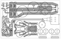
This is were I am sofar. Still have to cram all the components for the amplifier part on the board. The fuse holder has to be soldered on the solderside of the board. Maybe the Alps potmeter will have to move to the solderside also. I'm designing this board for 50V (HC-PS) and 100V (LC-PS) caps. The board should fit in the 110x105x165 alu housing that Hanzwillem is using alot. The image you see here is made in Autocad because I don't have a clue how to wirk with those PCB programs.
If you want I can post a PDF file with the image on a 1:1 scale.
Regards
If you want I can post a PDF file with the image on a 1:1 scale.
Regards
Attachments
Wim
The PCB "is" a eurocard format so it would fit in those alu boxes Conrad carries (52 29 70-06). That was the whole idea that got me started with this design. All wires shall be directly soldered to the board, no screw terminals and certainly no sub-d connector. The reason why the potmeter is on the board is to keep the signal path as short as possible. One just have to put an extention on the shaft of the potmeter to the front of the case. That's why I'm leaving a space of ±7mm so the shaft passes all the components on the board. Maybe I wasn't clear enough in the beginning.
The PCB "is" a eurocard format so it would fit in those alu boxes Conrad carries (52 29 70-06). That was the whole idea that got me started with this design. All wires shall be directly soldered to the board, no screw terminals and certainly no sub-d connector. The reason why the potmeter is on the board is to keep the signal path as short as possible. One just have to put an extention on the shaft of the potmeter to the front of the case. That's why I'm leaving a space of ±7mm so the shaft passes all the components on the board. Maybe I wasn't clear enough in the beginning.
My two cents:
You better move the tube as far away from electrolytics for not to heat them up.
You could consider to mount the tube socket on the solder side of the pcb. This would allow to install the board upside down and the tube as the only part looking upwards. Quite common practices, to avoid heating of the parts and a good base for pretty designs. If possible, choose a central place for the socket, in regard of design.
It's better to use the relay to ground the input of the chip during the mute phase. This way you avoid high inrush currents in the contacts of the relay. The resulting ~100mV offset during mute is no problem and this solution works absolutely pop free.
The only reason I placed the relay in the small version in the psu is very simple: no space in the amps enclosure.
/Edit: I miss the space for big coupling caps!
BTW: happy new year!
Franz
Another hint, maybe you can save some space on the board:
In this circuit, there is absolutely no need for regulated DC filament voltage! I just used it for the remote psu, to avoid hum induction into the power wires.
My single board amp is working with AC filament and absolutely no hum. Just use drilled wires and solder them nearby the filaments pin of the tube.
Now you are free to use another voltage for the delay/relay and can buy a more common version of relay.
Franz
You better move the tube as far away from electrolytics for not to heat them up.
I will keep that in mind. How hot does that tube get anyway?
You could consider to mount the tube socket on the solder side of the pcb. This would allow to install the board upside down and the tube as the only part looking upwards. Quite common practices, to avoid heating of the parts and a good base for pretty designs. If possible, choose a central place for the socket, in regard of design.
Good idea Franz. First I will try to fit everything on the board and after that the aesthetics will come into play
")
I miss the space for big coupling caps!
They have to be hardwired because of lack of space

Regards
I will keep that in mind. How hot does that tube get anyway?
I guess more than 100 degree C. It depends on the anode voltage eg. the total current, not just the filament.
They have to be hardwired because of lack of space
A second reason, to mount the tube upside down: you win space!
BTW: soundwise, it is good to use a input resistor >=22k and a coupling cap about 2.2uF for 22k or 1uF and 47k.
Franz
Franz G said:
I guess more than 100 degree C. It depends on the anode voltage eg. the total current, not just the filament.
Franz
hmmm, my tube does only get lukewarm even after 10 hours or so... I can easily touch it.
Hanzwillem
The housing I mentioned in post 225 from Conrad, do you know where I can find a drawing of it so I know how the inside looks like?
Franz
That sounds pretty hot to me Are you sure about that?
Regards
The housing I mentioned in post 225 from Conrad, do you know where I can find a drawing of it so I know how the inside looks like?
Franz
I guess more than 100 degree C. It depends on the anode voltage eg. the total current, not just the filament.
That sounds pretty hot to me
Are you sure about that?Regards
GeWa said:Hanzwillem
The housing I mentioned in post 225 from Conrad, do you know where I can find a drawing of it so I know how the inside looks like?
http://www2.produktinfo.conrad.com/datenblaetter/500000-524999/522970-da-01-de-Kuehlrippengehaeuse.pdf
Thats where this one gets in:
nr: 523232 and 523224
http://www2.produktinfo.conrad.com/datenblaetter/500000-524999/523232-da-01-de-Alu-Gehaeuse_1300.pdf
An externally hosted image should be here but it was not working when we last tested it.
nr: 523232 and 523224
http://www2.produktinfo.conrad.com/datenblaetter/500000-524999/523232-da-01-de-Alu-Gehaeuse_1300.pdf
It is made to house 160x100mm pcb. That's why it is a little over 100mm wide.
The picture explains it a bit. On the other side of the stripes on the side there are slots were the PCB can slide in. These are not that sturdy as the profiled cases. But I am very happy with it.
The picture explains it a bit. On the other side of the stripes on the side there are slots were the PCB can slide in. These are not that sturdy as the profiled cases. But I am very happy with it.
I have a lot of good relais, but they are 12VDC or 24VDC (i have to look tonight).
When the change can be made on the PCB for one of these voltages, ik can make a few of you happy with these relais for free. 6VDC relais are not very common (in Holland), and a good relais is not cheep.
When the change can be made on the PCB for one of these voltages, ik can make a few of you happy with these relais for free. 6VDC relais are not very common (in Holland), and a good relais is not cheep.
Hanzwillem
The datasheet shows two types of profiles. One with a width of 42mm and one with a width of 56mm. If there would exist a same type of profile with a width of 100mm that would be ideally. That 100mm would become the height of the case and the width would be whatever size of sheet you slide in in the top and bottom grooves. Does this make sense?
Regards
- Status
- This old topic is closed. If you want to reopen this topic, contact a moderator using the "Report Post" button.
- Home
- Amplifiers
- Chip Amps
- VBITNGC building & comment