But wouldn't life de dull without the little hickups?
Quite true (have you ever thought that a car couldn't go anywhere without friction?) but my life has more than enough hi-fi hiccups without trying to make the SI T-amp sound better than something that is clearly better!
")
Re: T-AMP RUINED
Now you know.
You need a dedicated support for the soldering iron.
You must worry about this before turning it on again and leaving it over the table.
Also for safety reasons.

Eggzy said:When modding the pcb I was distracted & the iron rested on the pcb underneath the chip...
Now you know.
You need a dedicated support for the soldering iron.
You must worry about this before turning it on again and leaving it over the table.
Also for safety reasons.
Member
Joined 2003
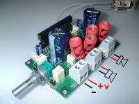
Well I spent the brokerage fees and got myself a T-amp. Very small PCB with what looks to me hand installed surface mount parts. I've searched through the forums and it looks like the standard modifications apply to this amp. Replace/rewire volume control and power switch. Replace input coupling caps, replace gain resistors, increase power supply capacitance, etc. I'm suprised because it looks like all the parts have been hand installed which is rare for such a cheap amplifier. By hand installed I mean poorly hand installed (peaks everywhere). I work in an environment where hand installed surface mount components are a must and must be soldered with very high tolerance. Think of soldering a 12th order filter of all surface mount 0402 parts that all look the same but are different values. Peaks are unacceptable where I work because our products work in the GHz frequencies. A little difficult, but not so much with the proper iron.
I got some 12V, 4.5A switching supplies from work that were in for RMA, and I think one of them will work sufficiently, although I worry that one day it might die or change voltage on me since it is an RMA part. I'll probably end up buying a 2500mA switching supply locally since they only cost $30CAD which really is the price of the amp but I want it to work to it's maximum potential and not blow up from a 16V supply that should be 12V.
I probably won't get to put this amp to any good use for a while since I bought it for my computer speakers whoch I haven't built yet, and probably won't be built until spring. I have 4 3" tang band drivers that are just great for some ELF1.5's although I don't have a heated garage and therefore won't want to build the boxes until spring because it's *******' cold outside.
Well, I'm off to bed...drunk...
Member
Joined 2003
Re: HELP!!! c12 what can I replace it with?
Hi Eggzy, do you mean C12 & C11? or are you refering to C10?
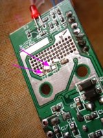
I removed C10 off the board completely as it sits right in the middle of the inductors and probably picks up RF.
I then decoupled C11 & 12 with a couple of 1000uf NRSK's, but after a re-think I replaced these with a couple of Pan FM 680's.
Don't remove C11 & 12!
You want low ESR caps for the job so try and get Pan FC's if you can't get anything else. Don't just slap anything out of the bag as it may make things worse. See the myriad of threads for info on how!
Lee
Eggzy said:...so could anyone advise me on a replacement for c12? I got lots of job lot bags of components from ebay. would a metal film type suffice? what would be stamped on the cap?
any advice welcome
Hi Eggzy, do you mean C12 & C11? or are you refering to C10?
I removed C10 off the board completely as it sits right in the middle of the inductors and probably picks up RF.
I then decoupled C11 & 12 with a couple of 1000uf NRSK's, but after a re-think I replaced these with a couple of Pan FM 680's.
Don't remove C11 & 12!
You want low ESR caps for the job so try and get Pan FC's if you can't get anything else. Don't just slap anything out of the bag as it may make things worse. See the myriad of threads for info on how!
Lee
what exactly is decoupling?
Thanks lostcause,
C12 & C11 are both goners they are [were] on the underside of the tripath chip, I suspect the soldering iron has done a lot of hidden damage too!...actually I think it's all beyond me so i'm ordering a 2020 kit from AUTOCOSTRUIRE it's 80 euros [are they fast deliverers?]
cheers
Eric
Attachments
Re: what exactly is decoupling?
Crikey, sounds like you've dived in with both feet! Don't give up hope yet though it's a tough little chip/board and those SMD's take some hammer. You can get replacement parts (if you have damaged any) from many sources. A lot cheaper than EUR80!
What about the AMP6 instead? I'm contemplating one as my next project.
Lee
Eggzy said:Thanks lostcause,
C12 & C11 are both goners they are [were] on the underside of the tripath chip, I suspect the soldering iron has done a lot of hidden damage too!...actually I think it's all beyond me so i'm ordering a 2020 kit from AUTOCOSTRUIRE it's 80 euros [are they fast deliverers?]
cheers
Eric
Crikey, sounds like you've dived in with both feet! Don't give up hope yet though it's a tough little chip/board and those SMD's take some hammer. You can get replacement parts (if you have damaged any) from many sources. A lot cheaper than EUR80!
What about the AMP6 instead? I'm contemplating one as my next project.
Lee
Re: AMP 6 ?
Difficult to tell, but it just looks like it's buried in the solder.
Should be able to dig it out and re-solder. Use tweasers to lift it off whilst applying some heat.
You can get a replacement from a multitude of places if you think it's toast. Seems a pity to bin it just for that?
Eggzy said:What another one!
thanks LC I'll check that out now
Difficult to tell, but it just looks like it's buried in the solder.
Should be able to dig it out and re-solder. Use tweasers to lift it off whilst applying some heat.
You can get a replacement from a multitude of places if you think it's toast. Seems a pity to bin it just for that?
Eggzy said:nah! it disintegrated and flew off into the wild blue yonder...LC could you tell me what the rplacement caps look like? what would the markings be on them? would the spec be critical?
are they little disc types or what?
cheers
eric
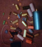
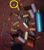
C11 is it's brother. They both decouple the power supply directly to the the respective left and right supply pins. I think it's an 0805 SMD (refers to its size) and has a value of 0.1uf but I'm not sure that will be marked on a cap that small. It needs to be as close to the pins as possible to reduce overshoot that's why they use SMD's. You can get a replacement easily and then replace C10 with a better one with a higher value (optional, but worth it). There is what seems to be an SMD in your bag but you need to know the value and without the kit you'll have no idea. They are damn cheap so pop into your nearest RS counter for one...or two...get a bag of em! Unless someone on the forum has a few they can send to you...ask in the marketplace....sorry I have a **** load of other stuff but not them. Pity because I work in Prescot and could have dropped some off!
Lee
Attachments
- Status
- This old topic is closed. If you want to reopen this topic, contact a moderator using the "Report Post" button.
- Home
- Amplifiers
- Chip Amps
- my t-amp experience