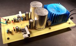
Hello everyone, I just thought that I would post some pics of my recently completed PSU for my preamp. It is based on discrete regulator design that can be found on Nuuk's site Decibel Dungeon.
This puts out 16.5V exactly, regulation seems to be rock solid. I have built the board around an AMVECO PCB mounted toroidal transformer, which feeds a dual bridge contructed of ISLR860's. The large cans are Rubycon 6800uF with the skins stripped, the rest of the caps are Panasonic FC's. The DC voltage from the rectifiers is fed into a pair of LM317/337 which regulates the voltage to around +/- 22V. This feeds a discrete regulator that brings it down to 16.5V. The grounds are seperate but could be connected depending on the application...and as you can see I still need to connect the output cables on the negative rail.
I had originally built this to go with my OPA627/Buf634 preamp...but I think it will soon be feeding my AD815 pre that I have in the works
Attachments
Banned
Joined 2002
Gcollier said:I had originally built this to go with my OPA627/Buf634 preamp...but I think it will soon be feeding my AD815 pre that I have in the works
A wise decision.
Gcollier said:I had originally built this to go with my OPA627/Buf634 preamp...but I think it will soon be feeding my AD815 pre that I have in the works
Would you be interested in any of those?
Attachments
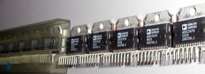
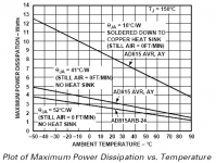
I didn't even know the AD815 was made in a package other than the soic. There is no max output current in the datasheet for either package, I guess you just need a big enough heatsink to dissipate the power. While looking for the datasheet for the AYS, I found that bgmicro has them in stock for $1.95 each for 1-9, $1.50 for 10-99 and $.99 for 100+. Now I have no more excuses not to build Carlos' preamp.
The discrete regulated power supply I built from Nuuk's webpage also gets 16.5 volt rails. Although mine is much uglier than yours. It's on a piece of scrap perfboard, and everything came out of the parts bin. Still, it should match well with Carlos' preamp.
The discrete regulated power supply I built from Nuuk's webpage also gets 16.5 volt rails. Although mine is much uglier than yours. It's on a piece of scrap perfboard, and everything came out of the parts bin. Still, it should match well with Carlos' preamp.
Attachments
Christer said:Do you have a schematic, or a link to one? I couldn't find any discrete regulator on Nuuks pages, but maybe I just missed it.
It's on Nuuks gainclone preamp page:
Preamp page
It starts at PSU part 2
Take
Christer said:Do you have a schematic, or a link to one? I couldn't find any discrete regulator on Nuuks pages, but maybe I just missed it.
http://myweb.tiscali.co.uk/nuukspot/decdun/gainclonepre.html
The link above will take you to the page wit the schematic. Scroll down and you will find it. I will post the board files later.
Peter, that certainly is an interesting package for the AD815 but I already designed my board around the SOIC version. I have no problem with SMD in fact I almost prefer it to through hole. Mind you heatsinking would be rather easy with those chips you showed.
As for plans to get some of these made I have none as I can etch all I need for myself, and it is only a simple single sided design. Once I post the board files you are free to do with them as you would like.
G.
butler853 said:I found that bgmicro has them in stock for $1.95 each for 1-9, $1.50 for 10-99 and $.99 for 100+. Now I have no more excuses not to build Carlos' preamp.
AFAIK, BG Micro has 22,000 of them in stock
Re: Re: Discrete Regulated Preamp PSU Pics

How did you get those????!

Peter Daniel said:Would you be interested in any of those?
How did you get those????!
Peter Daniel said:AFAIK, BG Micro has 22,000 of them in stock
Aaahhh...
Peter Daniel said:Carlos, since you introduced that chip to the forum, I wouldn't mind sending you a few samples...
Great, thanks for the offer, I'll send you a PM.
Peter Daniel said:(on condition you won't complain on pins layout)
I won't.

It's not as good in that respect as the SMD version, but it's much easier to put a heatsink there.
carlosfm said:
Great, thanks for the offer, I'll send you a PM.
I won't.
It's not as good in that respect as the SMD version, but it's much easier to put a heatsink there.
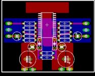
Carlos, is there any problem with creating a large power plane on the V+ pins to be used for heatsinking on the topide then routing the rest to the bottom of the board? Here is my current plan, I was going to mount a heatsink to the large copper area near the top of the board.
Attachments
For those interested, here is the Eagle BRD file...do with it as you please.
One word of caution...CHECK THE POLARITY OF YOUR DIODES before you install them in this board, if you are using ISLR860's like I did you need to reverse them from what is shown on the board!!!!! I will not be held responsible if you blow up your capacitors and your wife yells at you for getting smelly oil on everything! (not that it has ever happened to me )
)
G.
One word of caution...CHECK THE POLARITY OF YOUR DIODES before you install them in this board, if you are using ISLR860's like I did you need to reverse them from what is shown on the board!!!!! I will not be held responsible if you blow up your capacitors and your wife yells at you for getting smelly oil on everything! (not that it has ever happened to me
)G.
Attachments
Nice board, G'For those interested, here is the Eagle BRD file...do with it as you please.
Thanks.Steen
Gcollier said:Carlos, is there any problem with creating a large power plane on the V+ pins to be used for heatsinking on the topide then routing the rest to the bottom of the board?
Why don't you put the chip on the bottom side and use single layer, as you said?
Don't bother too much about a ground plane, specially around the signal pins, it creates capacitance.
Also, if you rotate the bypass caps by 90º (side by side) you will get the electrolythics much closer.
Your use of V+ for heatsinking is correct. But even then, the SMD chip gets quite warm.
You have space on that board for some poplyprop output dc coupling caps. These are optional. If you have input coupling caps on the power amp, no caps on the pre. Or vice-versa.
PS: Just before I hit 'submit' I've noticed that you are using that chip as a normal op-amp.
It won't work.
Have you seen my schematic?
You need a way to fine-tune DC-offset, that circuit I made also deals with the input dc-offset.
Otherwise you would have to use input dc-coupling caps to protect the volume pot.
Then you will muck up the performance of the pre by over-capping.
- Status
- This old topic is closed. If you want to reopen this topic, contact a moderator using the "Report Post" button.
- Home
- Amplifiers
- Chip Amps
- Discrete Regulated Preamp PSU Pics