Hi Marc, If you are refering to my layout, I am currently using all Evox Rifa MMK 5%, and they sound fine, with Rubicon ZLs for the 1000uf electros, I think they sound better than the Panasonics that generally seem a popular recommendation on the forum. (yes, one day I will try Black Gates") )
)
)Inverted LM 5875 - Class A
Hi,
I've tried biasing the output into class A and it makes a small but worth whiled improvement IMHO. I tried a 500Ohm resistor and I noticed an improved sound stage and a cleaner sound. I'm running a battery supply so regualtion is already pretty good - so YMV.
I then tried a pair of 150H chokes about 1K in resistance I had lying around from an old tube project and they sounded better again. CCS would be ideal. I don't think a lot current is needed to make things work.
I think this chip is a class AB but closer to B most of the time. I think pulling a little current just moves this chip away from the class B end of things. Less switching noise etc.
Cheers,
Anthony
hoxuanduc
I don't have one handy at the moment but just look at the link to Thorstens' Inverted amp.
http://home.attbi.com/~greggbaker/invertedLM3875.gif
The Changes I have made are to use a battery supply and to have a choke connected to the output to the -V supply to draw a little current out of the output stage at idle. Unless you have this kind of choke handy (150H @ 15ma) a CCS load would be the best thing to do here.
Great sounding amp.
Cheers,
Anthony
It looks better.
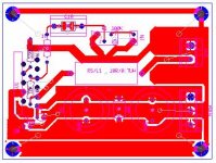
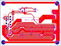
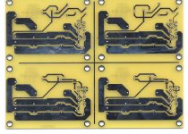
Sorry I didn’t mention it on the first place. Keep traces connecting the 1000uF caps wider. There is enough space. The gnd plane on the lower part of the board is not that necessary. No high impedance there. Same around the speaker output. Actually adds more capacitance to the load. If you are going to use gnd plane use it around the input stage (relatively higher impedance) rather then the power supply and the output (make those as wide as you can). Think of them as pipes. Any narrow section will limit the current flow. Also, the speaker and the input share the same gnd loop which is not good either. Run a separate trace (it doesn’t have to be wide because the currents are small there) from the gnd-star to the input gnd. And use that gnd connection to connect the gnd plain for shielding the input stage. I suggest you download and study AN-202 from the Analog Device site (http://www.analog.com). Do a search for it. It’s a pdf. And always refer to it. I find it very helpful.
Hope I didn’t confuse you more.
Greg
Attachments
Regarding out and in of the amp having common gnd loop: Works like this. If the pipe from the main to the house is not large enough, every time you take a shower upstairs and someone uses the washing machine downstairs at the same time you’ll be pretty upset because of the inconsistent water flow. So whenever the speaker needs more current the input of the amplifier will be affected. So the larger the pipes the less interference but the best is to use separate pipes from the main to the washing machine and to the shower.
The schematic is very simple so there are no reasons not to have perfect PCB layout.
Greg
The schematic is very simple so there are no reasons not to have perfect PCB layout.
Greg
Yeah, reminds me of college -- 8 of us in a suite -- if someone you didn't like was in the shower we'd coordinate flushing the toilets on a couple floors (this is the days before cell phones!).GregGC said:Regarding out and in of the amp having common gnd loop: Works like this. If the pipe from the main to the house is not large enough, every time you take a shower upstairs and someone uses the washing machine downstairs at the same time you’ll be pretty upset because of the inconsistent water flow. Greg
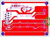
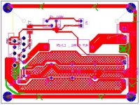
OK, You are almost there. If you leave the gnd connected to the four screws you may get some funky ground loops. I’d use paralel RC group to connect the star to the case and isolate the input connectors from the case too. I’d try to clean the area around the + and – power pins of the chip. I see some funky little trace there. You don’t need gnd plane there. The signal gnd looks fine. If you can make it a bit wider would be nice, but it should work fine the way it is. Keep it the same width all the way. On the picture it looks a bit narrower at the gnd star. Of course all the traces will be solid. I didn’t check the correctness of the connections (I don’t have the schematic) but I’m sure you’ve dun that.
Good work!
Greg
Good work!
Greg
Attachments
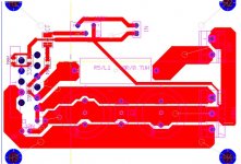
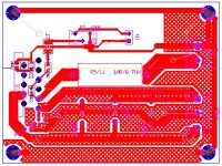
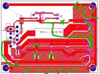
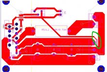
That looks great. O, I ask you to make the signal GND the same with. It just bugs me that way. It’s contra-intuitive. I know that it may work just as well, but I would correct it. And don't forget at the end the paralel RC to metal case and keep the input connectors isolated from the metal case.
I'd like to know how it sounds.
Greg
I'd like to know how it sounds.
Greg
Attachments
- Status
- This old topic is closed. If you want to reopen this topic, contact a moderator using the "Report Post" button.
- Home
- Amplifiers
- Chip Amps
- LM3875 Inverted Layout Comments Please