Well I haven't built it yet (but I am making progress) ") hopefully it will eventuate a little quicker than my MTM's are......
hopefully it will eventuate a little quicker than my MTM's are......
I decided to start a thread specifically about this amp so when I have questions I'll dump them in, whether asking questions this way will work or not I guess I'll have to see
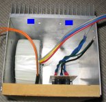
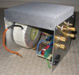
OK so I have just whipped up a dodgy chassis for it (first try at doing my own chassis, and this is only a test amp, so don't be too harsh.... the way it is going it'll probably end up in the ugly amp thread anyway ).... It's going to be relatively compact and I'm wondering about the orientation of the torroidal (its a 300VA one).
I've taken a pic of where I think I'll mount it ( the box is sitting on it's front in the pic)
The blue rectangles represent where the LM3886's (I'm doing it p2p) will be (the other option is to use a shortened version of the heat spreader that came with the sink and they will then be in roughly the same place but hanging down....
Now I read that torroids radiate pretty much in a narrow band straight through the center so I'm thinking that this orientation should be ok.... any cautions?
The main thing I don't like about this orientation is that it will not be symetrical ie the toroid is closer to one chip than the other, my original thought was to mount the torroid vertically on the front wall smack bang in the center.
I'm not worried about the asthetics as this amp will be used as a test bench amp
Tony.
hopefully it will eventuate a little quicker than my MTM's are......I decided to start a thread specifically about this amp so when I have questions I'll dump them in, whether asking questions this way will work or not I guess I'll have to see
OK so I have just whipped up a dodgy chassis for it (first try at doing my own chassis, and this is only a test amp, so don't be too harsh.... the way it is going it'll probably end up in the ugly amp thread anyway
).... It's going to be relatively compact and I'm wondering about the orientation of the torroidal (its a 300VA one). I've taken a pic of where I think I'll mount it ( the box is sitting on it's front in the pic)
The blue rectangles represent where the LM3886's (I'm doing it p2p) will be (the other option is to use a shortened version of the heat spreader that came with the sink and they will then be in roughly the same place but hanging down....
Now I read that torroids radiate pretty much in a narrow band straight through the center so I'm thinking that this orientation should be ok.... any cautions?
The main thing I don't like about this orientation is that it will not be symetrical ie the toroid is closer to one chip than the other, my original thought was to mount the torroid vertically on the front wall smack bang in the center.
I'm not worried about the asthetics as this amp will be used as a test bench amp
Tony.
Attachments
Thanks inguz
behind the front panel will certainly leave a lot more room around the chips, and also has the advantage that then both sides can be removed.... so that is probably a better bet. I'm a little paranoid about transformer induced noise as I have had problems with my other amp with this.
The base (as a mount point) is a bit tricky in that it makes it harder to mount my PS board because the base actually has the smallest dimentions (because I decided to put the heat sink on top) and the ps board wont fit beside the toroid!
Tony.
OK another question, (bet no one saw that coming
when implementing the signal ground star point in p2p what method do people use?
I'm thinking iether just solder all the leads together at one point (messy and possibly dangerous, due to possibility of shorts), or use some sort of anchor point and connect to that. How have you done it
the PS star point is taken care of already
Tony.
wintermute said:OK another question, (bet no one saw that coming
when implementing the signal ground star point in p2p what method do people use?
I solder all the leads together on the appropriate phono-out ground tag.
ok still on the signal ground......how important is it that all leads terminate at the exact same point?? I've got 7 gnd connections to do, I'm thinking of making pin 7 on the chip the star earth point, though this could result in not all leads soldered to the same exact point..... bad idea??? I'm thinking this may minimise the length of the runs to the signal ground star...
Every time I look at the chip I'm thinking "what have I got myself into" the pins are a bit closer together than what I'm used to for p2p work!! Tansistors with three pins can have their leads spread apart easily 
edit make that 6 I'll run the cz gnd separately back to the ps gnd actually thinking about it, should I run the supply bypass cap gnds back to the PS gnd separately too?
I'm using brians NI schematic..... I was originally thinking everything except the spkr returns terminated in a single star which then runs back to the PS ground..... now I'm thinking R2, NFB cap, input gnd, pin 7, local star with link back to PS. each bypass cap pair, wire back to ps. Cz wire back to ps. mute cap wire back to ps. I've just re-read the datasheet, and my the answer to my first question is probably a big fat "don't it's a bad idea"
Tony.
Every time I look at the chip I'm thinking "what have I got myself into"
the pins are a bit closer together than what I'm used to for p2p work!! Tansistors with three pins can have their leads spread apart easily edit make that 6
I'll run the cz gnd separately back to the ps gnd actually thinking about it, should I run the supply bypass cap gnds back to the PS gnd separately too?I'm using brians NI schematic..... I was originally thinking everything except the spkr returns terminated in a single star which then runs back to the PS ground..... now I'm thinking R2, NFB cap, input gnd, pin 7, local star with link back to PS. each bypass cap pair, wire back to ps. Cz wire back to ps. mute cap wire back to ps. I've just re-read the datasheet, and my the answer to my first question is probably a big fat "don't it's a bad idea"
Tony.
Keep going Tony, I'm a following Here's my LM3886 P2P work for some more data, and : Mark's intricate LM4780 work is inspiring.
Here's my LM3886 P2P work for some more data, and : Mark's intricate LM4780 work is inspiring.Thnaks Vikash I hadn't seen either yours or Marks , I've been trying to see as many as possible to give me inspiration I'm trying to get it as compact (around the chip) as I can without going crazy
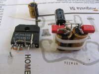
Decided to have three earth returns..... one is the PS bypass caps and the mute cap. One is the NFB, chip ground, and signal grounds, and the other is the output compensation, the speakers will also have their own runs.
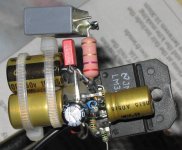
I've made some more progress, but when I checked my camera I don't have the latest pic (at GF's place now), I've attached the latest pic I took which has the rest of the FB components on the chip, I now have the input resistors and signal ground return wire too. only think left to do (for the first channel) is to put the output comp resistor and cap on, and solder the bypass caps and mute circuit to the chip
please excuse the poor quality and angle of this pic
Tony.
I hadn't seen either yours or Marks , I've been trying to see as many as possible to give me inspiration I'm trying to get it as compact (around the chip) as I can without going crazy Decided to have three earth returns..... one is the PS bypass caps and the mute cap. One is the NFB, chip ground, and signal grounds, and the other is the output compensation, the speakers will also have their own runs.
I've made some more progress, but when I checked my camera I don't have the latest pic (at GF's place now), I've attached the latest pic I took which has the rest of the FB components on the chip, I now have the input resistors and signal ground return wire too. only think left to do (for the first channel) is to put the output comp resistor and cap on, and solder the bypass caps and mute circuit to the chip
please excuse the poor quality and angle of this pic
Tony.
Attachments
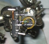
OK another status pic..... If I keep this up I might actually finish it
this one with input resistors and signal earth wire attached. Its amazing what you see when you take a closeup looks much more horible than it does to the naked eye I think I need to stop shrinking the heat shrink with the soldering iron tip too 
Tony.
this one with input resistors and signal earth wire attached. Its amazing what you see when you take a closeup
looks much more horible than it does to the naked eye I think I need to stop shrinking the heat shrink with the soldering iron tip too Tony.
Attachments
mabe I should have stuck to soldering
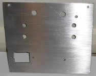
well I decided to do the rear panel...... holes went well except one where I don't think I centre punched deep enough and the bit must have slipped.... so one input socket is a bit wonky.....
but the real problem was with the hole for the power plug.... I got half way and my cheap nibbling tool decided that it had had enough of cutting 2mm aluminium and went on strike.... me being foolish and not thinking about it a little more carefully decided that the tungsten carbide cutting bit along with the mild steel case from the PC power supply that I got the connector out of would be real easy..... use the pc case as a template and just run around it..... hmmmm bad idea If I had have thought a bit longer I could have used my jig saw, or if I was really desperate chain drilled it, but I let speed seduce me and well now there is some extra ventilation around the power plug
Only other problem is that my fuse needs a 15mm hole and I don't have any drill bits that big!!
Oh well soldier on.....
oh and by the way there are some extra holes and a rounded off corner because this was a scrap piece of aluminium I had.....
Tony.
well I decided to do the rear panel...... holes went well except one where I don't think I centre punched deep enough and the bit must have slipped.... so one input socket is a bit wonky.....
but the real problem was with the hole for the power plug.... I got half way and my cheap nibbling tool decided that it had had enough of cutting 2mm aluminium and went on strike.... me being foolish and not thinking about it a little more carefully decided that the tungsten carbide cutting bit along with the mild steel case from the PC power supply that I got the connector out of would be real easy..... use the pc case as a template and just run around it..... hmmmm bad idea
If I had have thought a bit longer I could have used my jig saw, or if I was really desperate chain drilled it, but I let speed seduce me and well now there is some extra ventilation around the power plug Only other problem is that my fuse needs a 15mm hole and I don't have any drill bits that big!!
Oh well soldier on.....
oh and by the way there are some extra holes and a rounded off corner because this was a scrap piece of aluminium I had.....
Tony.
Attachments

Thanks Ropie It's not as good as I would have liked, but that's mainly to do with the fact that I forgot to clean up all of the component leads.... still haven't learned after more than 20 years .... some weren't tinning properly so I ended up with some blobs due to having to add more solder to get it to tin Hopefully the second channel will be better, if I clean up all the component leads.
Here is another pic. It's starting to look like an amplifier now!! though after my gaf with the power socket hole, I'm feeling a bit hesitant about doing the switch hole!!! it's only a small one though, 13mm X 18mm, so maybe I should try chain drilling and filing it.....
man I wish I had some decent metalworking tools I have my battery operated drill, a jig saw and the dremel (and a now defunct nibbling tool).... a drill press would be very nice. I was reading Vikashes case thread earlier, came across it when I did a search on finishing aluminium. I'm so jealous of all your equipment Vikash!!! I've always wanted a lathe, and you have lots of other goodies too
anyway time for me to head for bed I think.
Tony.
It's not as good as I would have liked, but that's mainly to do with the fact that I forgot to clean up all of the component leads.... still haven't learned after more than 20 years .... some weren't tinning properly so I ended up with some blobs due to having to add more solder to get it to tin Hopefully the second channel will be better, if I clean up all the component leads. Here is another pic. It's starting to look like an amplifier now!! though after my gaf with the power socket hole, I'm feeling a bit hesitant about doing the switch hole!!! it's only a small one though, 13mm X 18mm, so maybe I should try chain drilling and filing it.....
man I wish I had some decent metalworking tools
I have my battery operated drill, a jig saw and the dremel (and a now defunct nibbling tool).... a drill press would be very nice. I was reading Vikashes case thread earlier, came across it when I did a search on finishing aluminium. I'm so jealous of all your equipment Vikash!!! I've always wanted a lathe, and you have lots of other goodies too anyway time for me to head for bed I think.
Tony.
Attachments
Come on Vikash, surely you can turn up some nice equipment spikes or something To tell you the truth, I'm not sure what I would use a lathe for, I know there have been times I wanted one, but I think that was when I wanted to turn some special bolts for my Morris 1100.....
Haven't made any progress today, as I had to do my tax return, though I did just go out and buy some power cable, as the 12 gauge stuff I had was too heavy, and the thinner stuff (15A auto cable) was too stiff. So I got some nice 16 gauge super flexible OFC stuff..... might do a bit more this evening
Tony.
To tell you the truth, I'm not sure what I would use a lathe for, I know there have been times I wanted one, but I think that was when I wanted to turn some special bolts for my Morris 1100.....Haven't made any progress today, as I had to do my tax return, though I did just go out and buy some power cable, as the 12 gauge stuff I had was too heavy, and the thinner stuff (15A auto cable) was too stiff. So I got some nice 16 gauge super flexible OFC stuff..... might do a bit more this evening
Tony.
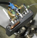
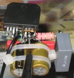
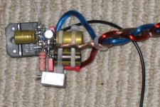
OK just attached the power leads..... I think this has been the hardest soldering job so far!!! I always dread soldering power leads on though
once again the camera doesn't hide any flaws and it also flattens the perspective making everything look like it is shorting together!! I think the closest gap between anything is at least 2mm, hopefully won't have any problems!
Tony.
once again the camera doesn't hide any flaws
and it also flattens the perspective making everything look like it is shorting together!! I think the closest gap between anything is at least 2mm, hopefully won't have any problems!Tony.
Attachments
- Status
- This old topic is closed. If you want to reopen this topic, contact a moderator using the "Report Post" button.
- Home
- Amplifiers
- Chip Amps
- Wintermute's Gainclone