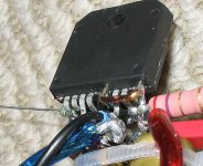
Passed
Well it passed the smoke test")
I've just powered it up and checked the dc offset on the output. 0.4mV!! is that too good to be true??? hoping that there isn't anything wrong
That is with an 8 ohm dummy load connected and no input connected.
Tony.
Well it passed the smoke test
I've just powered it up and checked the dc offset on the output. 0.4mV!! is that too good to be true??? hoping that there isn't anything wrong
That is with an 8 ohm dummy load connected and no input connected.
Tony.
Attachments
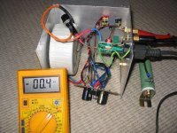
apparently the dc offset is real
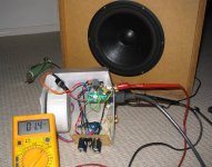
Have just hooked up to the pc sound card, and an old midrange driver I found out the front during a council cleanup and its playing music obviously with such a lousy driver I can make no comments on SQ but it works!!!!
with no input connected there is quite a bit of hum, but with the input connected no hum and just a very low level hiss
very happy about that as my 100W mosfet amp I have been struggling with hum for years...
I guess I should check the dc offset again with the pc conneted and nothing playing OK that looks a little more normal 30mv that is with no dc blocking cap on the input.
Is dc offset normally measured with or without an input connected??
Tony.
Have just hooked up to the pc sound card, and an old midrange driver I found out the front during a council cleanup and its playing music
obviously with such a lousy driver I can make no comments on SQ but it works!!!!with no input connected there is quite a bit of hum, but with the input connected no hum and just a very low level hiss
very happy about that as my 100W mosfet amp I have been struggling with hum for years...
I guess I should check the dc offset again with the pc conneted and nothing playing
OK that looks a little more normal 30mv that is with no dc blocking cap on the input. Is dc offset normally measured with or without an input connected??
Tony.
Thanks inguz
with shorted input the DC offset is 1.4mV can't complain about that!
also I hooked up one of my 3 ways (which has speaker protection) and it sounds very nice indeed I've only got 1000uF per rail per channel, but to me it isn't lacking bass at all.
I cranked it, and I think it was starting to clip on the transients, got a bit harsh sounding.... but the ps was staying pretty steady. dropped from 27.6V to about 26.8V (though I guess my DMM might have to slow a sampling rate to see what is really happening
all in all very happy, now I just have to do the other channel and finish up the chassis properly as it is a bit of a death trap as is
also this heatsink is way overkill played for 30 minutes on a bit higher than normal listening level and the chip didn't even get warm, and I don't even have any thermal grease on it yet! no switch on or turn off clicks or thumps either (especially surprising since at the moment the switch consists of pulling the plug out of the socket
gotta run now, need to get ready to go to the GF's place.
Tony.
with shorted input the DC offset is 1.4mV
can't complain about that! also I hooked up one of my 3 ways (which has speaker protection) and it sounds very nice indeed
I've only got 1000uF per rail per channel, but to me it isn't lacking bass at all. I cranked it, and I think it was starting to clip on the transients, got a bit harsh sounding.... but the ps was staying pretty steady. dropped from 27.6V to about 26.8V (though I guess my DMM might have to slow a sampling rate to see what is really happening
all in all very happy, now I just have to do the other channel and finish up the chassis properly as it is a bit of a death trap as is
also this heatsink is way overkill
played for 30 minutes on a bit higher than normal listening level and the chip didn't even get warm, and I don't even have any thermal grease on it yet! no switch on or turn off clicks or thumps either (especially surprising since at the moment the switch consists of pulling the plug out of the socket gotta run now, need to get ready to go to the GF's place.
Tony.
Attachments

Ropie said:Good work!
It's nice to see someone doing a p2p gainclone, not just going for the kit option
I think big heatsinks do improve sound so Iwouldn't worry about the overkill
Thanks Ropie
I wanted to do a p2p one and was even more determined when I read someones post that said people don't do them for the LM3886 cause there are too many components I guess if it runs cool then it is possibly having a positive effect!
Vikash said:big fat
What schematic did you use? And what what was the grounding arrangement you settled on. As soon as those heatsinks arrive I'll be putting mine together and I still don't understand proper grounding practices
Hi Vikash,
I used the BrianGT LM3886 one (which is basically pretty close to the datasheet), I think the differences are the inclusion of the 22k resistor on input, slight differences in the NFB resistors and the increase to 47uF of the NFB cap)... I had already decided to go with 47uF on the nfb cap and decided to go with Brians other changes as the kit gets a good rap
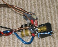
I have the star point in the middle of my power supply board. It is common to both channels, so I guess I won't know if it has worked properly till I make the other channel
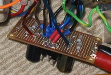
( the PS actually has separate rectifiers and cap banks for each channel but a single ground running down the middle...... did I post a pic of the PS earlier?? edit: don't have one, will have to take a better one with the bolt and bleed resistors installed... here is a post with the ps board ---> http://www.diyaudio.com/forums/showthread.php?postid=745654#post745654 before installing star point bolt... this was testing one side just in case I stuffed something up I didn't want to blow all my diodes or caps First thing on the star point is the transformer (center tap)* return, followed by the speaker return. Then I have the local power ground return, then the compensation cap return and finally the signal ground return. I'll elaborate below on the various local star points.
On the chip, I connected the +ve and negative leads of the two filter caps and also connected the mute caps earth connection at that point this made one local power star. That has one lead running back to the ps central star point. (Braided with the +ve and -ve rail wires).
I have a separate wire running back from the ground lead of the output compensation cap to the main star. I decided to do this based on the information in the datasheet.
I decided to use pin 7 as the local star point for the signal ground. It has the ground connection from the 22k input resistor, the ground connection of the NFB cap, and the ground from the input rca. The thin black wire is the run back to the PS star point.
This is my first try at star grounding, so I hope it is all still working properly when I hook up the other channel!! Pay to wait and see I think
Tony.
* I know it is not a center tap since it is a dual secondary toroidal, but I don't know the correct term in that instance.
Let me also show some pictures of my just finished P2P LM3886 Chipamp. It is based on the schematic of the Gaincard (see this thread ) plus the extra parts (mute, ground pin) due to the other chip.


The amp is mounted on a aluminium bookend which I use as a sort of testing jig for different amp configurations.
Mick
The amp is mounted on a aluminium bookend which I use as a sort of testing jig for different amp configurations.
Mick
Nice work Mick bit easier for you to change things on yours than on mine!! I made mine pretty much as a once complete don't touch it (except for the PS)!! Good to see I'm not the only one doing a p2p LM3886 Have you got anything supporting those big caps?? I'm thinking I'll put some silicon between my local decoupling caps and the heatsink so that there is less strain on the chip pins.
Vikash, here is a closeup of the PS (best pic I could find on the camera) not at home right now.... I thought I had a better one, but maybe I didn't take it.
Tony.
bit easier for you to change things on yours than on mine!! I made mine pretty much as a once complete don't touch it (except for the PS)!! Good to see I'm not the only one doing a p2p LM3886 Have you got anything supporting those big caps?? I'm thinking I'll put some silicon between my local decoupling caps and the heatsink so that there is less strain on the chip pins.Vikash, here is a closeup of the PS (best pic I could find on the camera) not at home right now.... I thought I had a better one, but maybe I didn't take it.
Tony.
Attachments
wintermute said:Nice work Mick
Tony.
I will make some kind of support for a final version. Not because of stability - the solder junction keeps the caps well in place - but because they can vibrate now. For testing it is ok.
Mick
resin!!! that might be a bit further than what I wanted to go certainly don't want to pot my transformer in
I think that (apart from the resistors) the chips were the cheapest part of this amp!!! I haven't really been keeping a track of the cost, but I rekon it would be approaching $150 Aus (though that's partly because the caps I had to buy in lots of 5, and the transformer was a bit more expensive than I originally intended probably getting close to half the cost).
Tony.
certainly don't want to pot my transformer in I think that (apart from the resistors) the chips were the cheapest part of this amp!!! I haven't really been keeping a track of the cost, but I rekon it would be approaching $150 Aus (though that's partly because the caps I had to buy in lots of 5, and the transformer was a bit more expensive than I originally intended probably getting close to half the cost).
Tony.
Vikash said:big fat
And what what was the grounding arrangement you settled on. As soon as those heatsinks arrive I'll be putting mine together and I still don't understand proper grounding practices
Vihash, I have just put a detailed documentation of the building procedure of my "Gaincard copy" on my website. Please have a look at
this site
A hopefully very clear description of the grounding scheme is included.
Comments are welcome.....
Mick
Vikash said:Excellent pics and write up Mick. The only things you haven't mentioned are the DC offset, and what the amp sounds like
The DC offset is rather high. 90 and 48 mV. But I tested with **** speakers and later on with my Dynaudio test speakers and found no movement of the cones when switching the amp on, or any other problems. So I decided not to take any actions to reduce the DC offset.
I like the sound very much as far as I can judge it from listening to my test system. I will let it run for a week or so before I move it to my main system.
Mick
Edit: I was not aware that c r a p is a "bad word". It was removed by the system, however. I'd just like to let you know that I did not test it with **** speakers.
Yes and we don't take kindly to people spacing things out to get past the filter!
I noticed you have an input connected in the pic showing your DC offset measurement. Just wondering if this was connected on the other end and potentially adding to your offset?
My memory escapes me, but does grounding have an effect on DC offset?
I noticed you have an input connected in the pic showing your DC offset measurement. Just wondering if this was connected on the other end and potentially adding to your offset?
My memory escapes me, but does grounding have an effect on DC offset?
Vikash said:Yes and we don't take kindly to people spacing things out to get past the filter!
I noticed you have an input connected in the pic showing your DC offset measurement. Just wondering if this was connected on the other end and potentially adding to your offset?
My memory escapes me, but does grounding have an effect on DC offset?
So it IS a bad word??? A REALLY bad word???
I have tried with and without a source connected. The result was identical, but this is understandable as I have a DC blocker on the input. The offset I measure is a matter of the chip itself and the parts connected. However, I just leave it as it is.....
Mick
Better be careful Mick you might get thrown in the sin bin for BAD language sometimes I think that the auto sensor is a bit sensitive, but then there is a very wide demographic of people here, so what seems tame to us could be very offensive to someone else.
I've been thinking I should do a proper writeup on mine too, I've kinda been doing it visually with this thread, but a bit more explanation would be good
Did you use generic brand components in yours Mick, or more esoteric ones? Mines a bit of a mix, but nothing outrageous.
I have made very little progress today, I think I drilled 6 holes and chain drilled and filed the hole for the power switch (it's much better than when I attacked the power socket hole with the dremel!). Oh that was the other thing, I drilled the hole and mounted the power indicator neon.... no blue LED's in this gainclone  (I'm assuming it is neon as it runs direct of 240V, and the multimeter shows no continuity, jaycar sell it as an LED).
Tony.
sometimes I think that the auto sensor is a bit sensitive, but then there is a very wide demographic of people here, so what seems tame to us could be very offensive to someone else. I've been thinking I should do a proper writeup on mine too, I've kinda been doing it visually with this thread, but a bit more explanation would be good
Did you use generic brand components in yours Mick, or more esoteric ones? Mines a bit of a mix, but nothing outrageous.
I have made very little progress today, I think I drilled 6 holes and chain drilled and filed the hole for the power switch (it's much better than when I attacked the power socket hole with the dremel!). Oh that was the other thing, I drilled the hole and mounted the power indicator neon
.... no blue LED's in this gainclone (I'm assuming it is neon as it runs direct of 240V, and the multimeter shows no continuity, jaycar sell it as an LED).Tony.
- Status
- This old topic is closed. If you want to reopen this topic, contact a moderator using the "Report Post" button.
- Home
- Amplifiers
- Chip Amps
- Wintermute's Gainclone