maria_andersson said:if less is added then less is too be understood, which I assume is the hard part
Very well put, may become a classic audio phrase in the future.
An input buffer makes a high impedance input which makes it much easier to interface any signal source and the buffer can drive any load like a low impedance inverting gainclone.maria_andersson said:I think Jacco agreed to your idea with the input buffer PA. Does an input buffer like that help to keep the feed from being 'drained' if you use long interconnects? Or is it just a better DC blocker?
If you have an input buffer you can also add a volume pot without any special considerations.
Jacco: thanks (I guess)
PA: OK, I get it, I think. A high impedance load is easier load for the preamp since it will 'drain' less current. A current drain would alter the signal amplitude right? Same as with low impedance speakers I guess. In general you would want to have as high impedance as possible on the input side?
Eitherway I will incorporate the buffer in the PCB and see what it looks like.
Hello
Well in your case I guess P-A ment AD8610 (the single version of 8620) P-A used the dual one because he used one channel as the inputbuffer and the otherone as the servo ( i think).
Nevertheless, it's still soic so look at OPA627 & OPA134 from TI, 627 = better 134 = cheaper
/Tobias
Well in your case I guess P-A ment AD8610 (the single version of 8620) P-A used the dual one because he used one channel as the inputbuffer and the otherone as the servo ( i think).
Nevertheless, it's still soic so look at OPA627 & OPA134 from TI, 627 = better 134 = cheaper
/Tobias
There are lot's of good opamps but it's also a matter of getting them.
OPA134 is a "Volvo S80 with all the extras" and can be bought at www.elfa.se
OPA134 is a "Volvo S80 with all the extras" and can be bought at www.elfa.se
") , the 627 was quiet a bit too expensive for my budget,
, the 627 was quiet a bit too expensive for my budget, 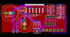
- Status
- This old topic is closed. If you want to reopen this topic, contact a moderator using the "Report Post" button.
- Home
- Amplifiers
- Chip Amps
- Feedback on Gainclone PCB layout Wanted