Beforehand I apologize for quality, the original in Russian
Adjustment of the amplifier begin with check of absence of mistakes in editing. Then include a feed and selection of resistor R3 establish on a source of transistor VTI a voltage 8...9 Â. On an input of 1000 Hz a voltage 260 ì submit from the generator a signal frequency, and to an output connect an oscillograph and the high-resistance voltmeter. Cursors of regulators of loudness and a timbre establish in the top position under the circuit, and a regulator of balance - in average. Arranged resistor R34 establish on an output of the amplifier a voltage 1 V and increase a voltage of the generator until there will come bilaterial restriction of a signal. Symmetry of restriction of a signal on an output of the amplifier achieve selection of resistor R12. If necessary select also resistor R29 more precisely.
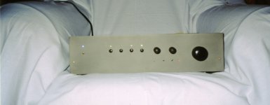
SB1 - loudness
SB2 - mono
SB3 - the filter of low frequencies (10kHz)
SB4 - pure direct
SB5 - the filter of high frequencies (60Hz)
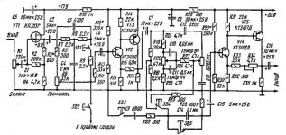
Adjustment of the amplifier begin with check of absence of mistakes in editing. Then include a feed and selection of resistor R3 establish on a source of transistor VTI a voltage 8...9 Â. On an input of 1000 Hz a voltage 260 ì submit from the generator a signal frequency, and to an output connect an oscillograph and the high-resistance voltmeter. Cursors of regulators of loudness and a timbre establish in the top position under the circuit, and a regulator of balance - in average. Arranged resistor R34 establish on an output of the amplifier a voltage 1 V and increase a voltage of the generator until there will come bilaterial restriction of a signal. Symmetry of restriction of a signal on an output of the amplifier achieve selection of resistor R12. If necessary select also resistor R29 more precisely.
SB1 - loudness
SB2 - mono
SB3 - the filter of low frequencies (10kHz)
SB4 - pure direct
SB5 - the filter of high frequencies (60Hz)
Attachments
i d suggest you to be extra careful while using these chips form STK corp, as they ll blow up before u know and in return will destroy the speaker too.

For those who r interested in schematics and layouts of STKs they can check their local markets for books by STK corp in which schematics and layouts of all STK series are there and if i remeber right they(books) ve been on sale since 90s.
Cheers
For those who r interested in schematics and layouts of STKs they can check their local markets for books by STK corp in which schematics and layouts of all STK series are there and if i remeber right they(books) ve been on sale since 90s.
Cheers
Chaom1 said:But do you have the pcb to share?
Unfortunately is not present
Professor said:I did not try other types of microcircuits but there is very good variant of the amplifier on STK465
I get a problem with the STK465.
The device I tried to replace was marked STK465 with a B on. ( that one is defective. )
The new one is not marked with the B, just STK465. When I measure the voltage at pin 4 and pin 13 with respect to ground, I got between +3.5 to +4 volts.
On the STK465B I got -1.4 volts, what I expected to measure according to the internal schematics.
I have tryed with 2 STK IC's, and they both get about the same readings.
Output (pin 7 or 11) from the amp. is very distorted. It clips at the negative half wave at low levels. At full power it looks like crossover distortion on the oscilloscope.
Anyone have som suggestions?
Hello She
Sorry for the late delay, I was really busy lately, any way, there are many points to talk about in your schematics:
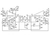
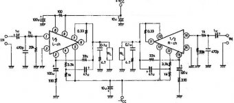
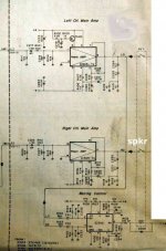
There are two resistors missing, one between pins 6 and 7, its value is 0.33 ohm/5 watt, and the output signal is taken from pin 7. The other one between pins 10 and 11, and the output signal is taken from pin 10.
Also you have to use a resistor of about 100 ohm/0.5 watt between the tr401 emmiter and pin 8, also connect a 100uF/100V capacitor from pin 8 to GND, as in the original schematics, the transistor is meant to avoide the pop up at power switch on, hence it introduces a small delay, that is very impressive in deed. Any way, you better add the resistor and capacitor I told you about, as pin 8 is the source of +ve power supply for the differential input transistors, and the driver transistors, hence, the 100 ohm resistor is meant to serve as a current limiter too.
There are also 8pF capacitors between pins 2 & 4, and between pins 13 & 15. They are used to enhance stability at high frequency, and avoide oscillation.
Regarding the TA7317, I have already downloaded the datasheets, and I still try to understand how this IC is really working, though, I think its very good choice for an amplifier protection, it can sense both AC & DC +/- swings. Its very good in deed. But I still don't understand why using -20V at pin 1 through R126....
While testing, avoid connecting TA7317 to your circuit, and test the STK alone. Also, try to measure the voltage at pin s 6 and 11, also at pins 7 and 10
Good luck
Sorry for the late delay, I was really busy lately, any way, there are many points to talk about in your schematics:
There are two resistors missing, one between pins 6 and 7, its value is 0.33 ohm/5 watt, and the output signal is taken from pin 7. The other one between pins 10 and 11, and the output signal is taken from pin 10.
Also you have to use a resistor of about 100 ohm/0.5 watt between the tr401 emmiter and pin 8, also connect a 100uF/100V capacitor from pin 8 to GND, as in the original schematics, the transistor is meant to avoide the pop up at power switch on, hence it introduces a small delay, that is very impressive in deed. Any way, you better add the resistor and capacitor I told you about, as pin 8 is the source of +ve power supply for the differential input transistors, and the driver transistors, hence, the 100 ohm resistor is meant to serve as a current limiter too.
There are also 8pF capacitors between pins 2 & 4, and between pins 13 & 15. They are used to enhance stability at high frequency, and avoide oscillation.
Regarding the TA7317, I have already downloaded the datasheets, and I still try to understand how this IC is really working, though, I think its very good choice for an amplifier protection, it can sense both AC & DC +/- swings. Its very good in deed. But I still don't understand why using -20V at pin 1 through R126....
While testing, avoid connecting TA7317 to your circuit, and test the STK alone. Also, try to measure the voltage at pin s 6 and 11, also at pins 7 and 10
Good luck
The circuit I use have been working fine for more than 10 years.
Why do I have to change the circuit, when I am replacing the "thick film hybrid IC" STK465 B with a new one that is marked STK465 ?
Has the producer changed someting inside the STK465 that results in the problems that I got ?
Why do I have to change the circuit, when I am replacing the "thick film hybrid IC" STK465 B with a new one that is marked STK465 ?
Has the producer changed someting inside the STK465 that results in the problems that I got ?
- Status
- This old topic is closed. If you want to reopen this topic, contact a moderator using the "Report Post" button.
- Home
- Amplifiers
- Chip Amps
- Stk4191v