To anyone who has not seen it, Nuuk's buffered passive pre can be seen at http://myweb.tiscali.co.uk/nuukspot/decdun/gainclonepre.html
While it is not a difficult design to build on breadboard, a PCB is always easier. Attached is a copy of a slightly modified schematic which adds an input resistor and an input cap as well as small rail caps. You can search this forum to find explanations for each of those changes.
While it is not a difficult design to build on breadboard, a PCB is always easier. Attached is a copy of a slightly modified schematic which adds an input resistor and an input cap as well as small rail caps. You can search this forum to find explanations for each of those changes.
Attachments
So, I decided to make said PCB design. The input cap is sized for either a Blackgate N series 1uF cap, or a Solen 1uF cap. The output cap is sized for a 4.7uF Solen cap. The rail caps are sized for Wima 0.1uF caps. All resistor spots are over sized such that they hold Kiwame 2W resistors.
As soon as it seems that the board is correct, I'll post the ExpressPCB files.
edit: nothing like posting to find stupid mistakes. corrected pcb attached.
-d
As soon as it seems that the board is correct, I'll post the ExpressPCB files.
edit: nothing like posting to find stupid mistakes. corrected pcb attached.
-d
Attachments
Hey dsavitsk! Nice work 
I'll bet many would like to build that one.
Actually I found that circuit interesting myself so I did a "mono"-pcb some weeks ago to have as a addon-pcb for my "Mr_ED" pcb, have't build it though.")
http://www.ettnet.se/~tobias/diy/lm3886/gcbuffer1.jpg
I'll bet many would like to build that one.
Actually I found that circuit interesting myself so I did a "mono"-pcb some weeks ago to have as a addon-pcb for my "Mr_ED" pcb, have't build it though.
http://www.ettnet.se/~tobias/diy/lm3886/gcbuffer1.jpg
tobias_svensk said:
Any chance to get the actual pcb layout?
Why didn't you try to include the discrete regulators at Nuuk's too?
Carlos
carlmart said:
Why didn't you try to include the discrete regulators at Nuuk's too?
Are you asking me or dsavitsk?
I have regs onboard.
http://www.ettnet.se/~tobias/diy/lm3886/gcbuf.jpg
Cheers
carlmart said:Why didn't you try to include the discrete regulators at Nuuk's too?
I guess that's for me ...
Partly to keep the PS seperate, partly cause I ran out of room. ExpressPCB has a deal where one can get 3 boards of this size for $51. Any bigger, however, and the price goes up.
Anyway, here is a small change to add the ability to use Blackgate N 4.7uF caps on the output.
Attachments
tobias_svensk said:
Are you asking me or dsavitsk?
I have regs onboard.
http://www.ettnet.se/~tobias/diy/lm3886/gcbuf.jpg
Tobias,
Yes, you have regulators. But they are LM3X7s. So I asked why you didn't use the discrete ones suggested by Nuuk.
Carlos
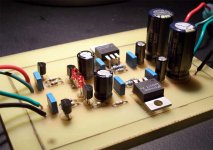
While we are looking at Nuuks buffered pre I figured I would post a pic of my board based on his discrete regulator. This was built following the schematics from his site. As it is, it puts out +/-16.5V rock steady. The LM317/337 "preregulate" the voltage to 22V before it hits the discrete regulators. I have seperate grounds for the +/- rails, although this is likely unnecessary.
This is going to be connected to my OPA637/BUF634 preamp that I completed a while back.
G.
This is going to be connected to my OPA637/BUF634 preamp that I completed a while back.
G.
Attachments
Thanks dsavitsk, I was looking for that.
Would it be possible to show the the components values on your schematic? Just to be sure, so I won't make any mistake.
In the decibel dongeon page the guy say that he use 10k pots.
That is what I already have, and a very good quality one. Hope I can use it.
Would it be possible to show the the components values on your schematic? Just to be sure, so I won't make any mistake.
In the decibel dongeon page the guy say that he use 10k pots.
That is what I already have, and a very good quality one. Hope I can use it.
PierreG said:Thanks dsavitsk, I was looking for that.
If you are going to use the PCB, you should do a thorough check for errors. I think it is correct, but there are no guarantees. (I'll put up the board files later today.)
PierreG said:Would it be possible to show the the components values on your schematic? Just to be sure, so I won't make any mistake.
In the decibel dongeon page the guy say that he use 10k pots.
That is what I already have, and a very good quality one. Hope I can use it.
Most of the component values can be read from Nuuk's wesite. The ones that cannot are as follow:
- The input resistor should be about 1K, though the value is not critical.
- The input cap can be anything from .47uF and up. I think that 1uF is a good choice as it keeps the corner frequency and any phase distortions well below 20Hz.
- The rail caps I used were 0.22uF. 0.1uF should be fine as well, but a bit of experimentation might be in order as the value will depend upon your PS and how far it is from the buffer.
If you search through some threads, there are some comments about how changing R5 can change the sonic character, so that is another part with experimenting with.
A 10K pot is a good choice here. In fact, with a 10K pot you can probably omit the input cap. I found that there was noise on the pot with a 50K pot and no cap, but with a 10K pot there is no noise.
Last, as I mentioned, I made the resistor spots big enough for large carbon film resistors (Riken, Kiwame) or tantalums. My experience was that I built this buffer with Holcos and it sounded horrible, but with high quality carbons it sounds great. YMMV.
-d
Good work guys but I should say that Andrew Rothwell who gave me that circuit would not be impressed to see electrolytic caps used in the signal path!
OK, so you have to keep the PCB size down for reasons of cost but isn't sonic quality the goal here?
I confirm that with a 10K pot, you don't need the input cap.
OK, so you have to keep the PCB size down for reasons of cost but isn't sonic quality the goal here?
I confirm that with a 10K pot, you don't need the input cap.
Nuuk said:Good work guys but I should say that Andrew Rothwell who gave me that circuit would not be impressed to see electrolytic caps used in the signal path!
I wouldn't either, but since people here love their blackgates, I left in the option. If you look, there are extra pads and there is room for at least polyprops (it is sized for Solens), and perhaps a smaller film and foil. The input caps should fit fine on the board. The output caps probably need to je just off the side.


I wouldn't either, but since people here love their blackgates,
Perhaps it is worth saying again then. There are lots of newbies around here who often read something and then take it as gospel without understanding the context!
Black Gates are good electrolytic capacitors but unless space is restricted, polypropylene film caps sound better!
I fear that I may be partly responsible for this because my original Gainclone used Black Gate NX's as the input DC blocking capacitors. But that was because I was using parts that I already had to keep the cost down, and because I had hardly any space in those small pods.
10k PEC pot?
hello,
you mentioned that one can purchase the 10K PEC pot on digikey.
but i'm assuming you mean the non-audio version? (i did a quick check, and it seems the panasonic Pot was only available for audio)
otherwise, nice webpage regarding the preamp.
i think i'll make one right now.
cheers,
hello,
you mentioned that one can purchase the 10K PEC pot on digikey.
but i'm assuming you mean the non-audio version? (i did a quick check, and it seems the panasonic Pot was only available for audio)
otherwise, nice webpage regarding the preamp.
i think i'll make one right now.
cheers,
- Status
- This old topic is closed. If you want to reopen this topic, contact a moderator using the "Report Post" button.
- Home
- Amplifiers
- Chip Amps
- PCB for Nuuk's Buffer