I have been building an audisector gainclone over the past few weeks with all of te standard parts checked everything switched it on and one of the LM3875's Blew, examined it closer and checked all wiring which was correct, noticed the chip was cracked in multiple places thoght I had overtightened it so I bought 2 more LM3875T's from Farnell. The other channel works perfectly so no problems there.
Unsolder the LM3875 and put a new one, made sure I insulated it and put eveything back, power on and same thing happend, noticed that the diodes were round the wrong way on the board so i have just switched them around. Measured the voltages in the rectifier which i am suspicious of the reading are 25.8v and 20v and on the channel which is working fine it is 25.8v and 25.8v is this the problem and if it is how can I correct it? if it was the diodes were round the wrong way is it safe to connect my other chip?
http://img327.imageshack.us/img327/346/blown3pr.jpg
Picture of blown chip.
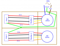
Diagram of how it is wired.
Many Thanks
Unsolder the LM3875 and put a new one, made sure I insulated it and put eveything back, power on and same thing happend, noticed that the diodes were round the wrong way on the board so i have just switched them around. Measured the voltages in the rectifier which i am suspicious of the reading are 25.8v and 20v and on the channel which is working fine it is 25.8v and 25.8v is this the problem and if it is how can I correct it? if it was the diodes were round the wrong way is it safe to connect my other chip?
http://img327.imageshack.us/img327/346/blown3pr.jpg
Picture of blown chip.
Diagram of how it is wired.
Many Thanks
Attachments
I reconnected everything and it hasn't blown up, so the reversed diodes were the problem, Now the only problem is that there is 25v on the output so something is obviously wrong. I think this is because I desoldered everything off the amp so many times that the solder pads for the components have come off and that the solder doesnt really stick to anything anymore, I hope there is a diagram for peter daniel pcb, So I am now going to do that channel on prototype board.
Thanks,
Thanks,
Did you change the smoothing cap too on that rail?dome406 said:Measured the voltages in the rectifier which i am suspicious of the reading are 25.8v and 20v
Sounds like you could have blown more than just the chip. You need to check all the components with a DMM and thoroughly check the soldered chip pins are not touching each other etc.dome406 said:Now the only problem is that there is 25v on the output so something is obviously wrong.
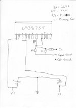
I have checked all of the resistors but I dont know how to check capacitors and I have checked the diodes, there doesn't look like any shorts but I will go and check again the smoothing caps on the power supply are the standard small ones from the kit, when it is connected to the amplifier board it give the correct voltages. On the rectifiers I am using 8 diodes and a 750R resitor and an LED and 2, 10uf 50v caps
BTW the LED on the dodgy rectifier takes a very long time to fade if that helps.
Thanks very much,
BTW the LED on the dodgy rectifier takes a very long time to fade if that helps.
Thanks very much,
You need to debug from the beginning. Check your trx secondaries have the correct/matching AC, then check DC output from the rectifier bridge before the cap, then with the cap. One of those must be the culprit for the irregular rail voltage. Once you have correct output from the rectifier PCB then you can concentrate on the problem on the amp board:
If the rectifiers were mounted incorrectly, then you may have damaged the caps on the amp board too . I would start by measuring the pins at the opamp to ensure the correct voltages are being fed in. You need to be very careful doing this so as not to create a short with the probe.
If the rectifiers were mounted incorrectly, then you may have damaged the caps on the amp board too . I would start by measuring the pins at the opamp to ensure the correct voltages are being fed in. You need to be very careful doing this so as not to create a short with the probe.
")
- Status
- This old topic is closed. If you want to reopen this topic, contact a moderator using the "Report Post" button.
- Home
- Amplifiers
- Chip Amps
- My Gainclone Problem