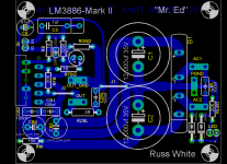
Ok, so I got a little bored today and decided I would layout a PCB pretty much to the datasheet of a non-inverting LM3886 amplifier using some of the techniques I have gleaned so far.
The idea behind this is a one board monobloc amplifier, with as optimal ground paths as I could manage and seperate signal ground. Everything is on the PCB but the trafo.
It includes an output zobel, but that can be omitted, it also includes a power LED section but that can omitted as well.
So what do you think?
Ohhh, yeah the name... Well I called it "Mr Ed" after a friend who sponsored the caps for this project... hmmmm who could that be")
Cheers!
Russ
The idea behind this is a one board monobloc amplifier, with as optimal ground paths as I could manage and seperate signal ground. Everything is on the PCB but the trafo.
It includes an output zobel, but that can be omitted, it also includes a power LED section but that can omitted as well.
So what do you think?
Ohhh, yeah the name... Well I called it "Mr Ed" after a friend who sponsored the caps for this project... hmmmm who could that be
Cheers!
Russ
Attachments
I'd buy a handful if they were for saleRuss White said:So what do you think?
/U.
A horse is a horse, of course of course
Oh, Hi, Wilbur
I thought I was taking a break from yard work. Look what I found!
Would there be any value in developing a ~12V source for powering a thermister controlled cooling fan? I'm thinking of a cpu heatsink/fan combination.
If the production run of boards were "panelized" with the LM3886 along the outside edge and scored, they could be left together so the row of monoblocks could share a common heatsink, or broken apart.
Or, how narrow can the board be? Would 3 chips fit on one of those neat barred boss heatsinks?
Let's get some feedback on the interest in any of these. I'm promoting ideas for discussion, not exhaust the golden goose.
the 100nF bypass caps should be ceramic, not film (I can hear the groans now.)
220uF is a bit of overkill -- you can use 10uF.
make sure that the via's for the ground jumper (J1) are big enough to handle the current flowing on this node.
one final thing -- make sure that there is enough clearance between the big electrolytics so that you can wedge a screwdriver in there !!! elsewise you'll have a devil of a time attaching the chip to the heatsink.
jackinnj said:the 100nF bypass caps should be ceramic, not film (I can hear the groans now.)
220uF is a bit of overkill -- you can use 10uF.
make sure that the via's for the ground jumper (J1) are big enough to handle the current flowing on this node.
one final thing -- make sure that there is enough clearance between the big electrolytics so that you can wedge a screwdriver in there !!! elsewise you'll have a devil of a time attaching the chip to the heatsink.
I have tested with 220uf, I like it thanks.
But cetainly anyone could put whatever they like there. I have tried 47uf there as well, and that also was fine. So I agree there is some room to 'speriment.Cermic caps would fit fine on those pads, but I would use metal film. But hey its all good.
As far as mounting on the heatsink I use one of those right angle screw drivers which look like an "L". Its the arrangement as on Mauro's boards. No prblem mounting the heatsinks.
There is no gap there on purpose, those caps are blocking EMI from the rectifier bridge. Why let some leak through?I have already built two of these. I will post more later.
Cheers!
Russ
Re: A horse is a horse, of course of course
Hmmm wilber.... hey that might stick...
I will look into the aux power thing.
Yeah panelizing is a good idea.
They are too wide for three, but two would definitely work.
Those barredboss sinks rock. Just recieved 6 more. Black anodized.
bg40403 said:Oh, Hi, Wilbur
I thought I was taking a break from yard work. Look what I found!
Would there be any value in developing a ~12V source for powering a thermister controlled cooling fan? I'm thinking of a cpu heatsink/fan combination.
If the production run of boards were "panelized" with the LM3886 along the outside edge and scored, they could be left together so the row of monoblocks could share a common heatsink, or broken apart.
Or, how narrow can the board be? Would 3 chips fit on one of those neat barred boss heatsinks?
Let's get some feedback on the interest in any of these. I'm promoting ideas for discussion, not exhaust the golden goose.
Hmmm wilber.... hey that might stick...
I will look into the aux power thing.
Yeah panelizing is a good idea.
They are too wide for three, but two would definitely work.
Those barredboss sinks rock. Just recieved 6 more.
Black anodized.NI 3886 PCB
I must admit, I am a little excited about your layout Russ. I like the idea of putting the PSU on the amp board, even though the trend has been to separate the two to allow for separation and prevent noise. I'm confident that with the proper arrangement of components this amp will be very quiet. I also like the fact that it is single-sided.
I was quite impressed by the tiny 3886 PCB you posted a while ago, but was wondering when you'd put Mauro's invaluable feedback (a la your interpretation of his my_ref rev. C) into a the more typical 3886 design.
Anyway, I have a simple question about the connectors you choose. Does it make sense to use one connector for the output/output ground instead of two. I'm sure there is a good reason for your doing this, but please enlighten me. I'm just starting to create my own PCBs in Eagle and appreciate any insight.
Thanks,
Brian
Re: NI 3886 PCB
Hi Brian, you are very kind. The connectors I chose for out and out ground are the faston type simply because they have more current handling capacity. Honestly you could probably get by with pin headers, but I like the more solid connection of the fastons. one other option I considered was just putting wire pads there, but I like to be able to quickly disassemble and reassemble an amp.
Cheers!
Russ
balance said:
Anyway, I have a simple question about the connectors you choose. Does it make sense to use one connector for the output/output ground instead of two. I'm sure there is a good reason for your doing this, but please enlighten me. I'm just starting to create my own PCBs in Eagle and appreciate any insight.
Thanks,
Brian
Hi Brian, you are very kind. The connectors I chose for out and out ground are the faston type simply because they have more current handling capacity. Honestly you could probably get by with pin headers, but I like the more solid connection of the fastons. one other option I considered was just putting wire pads there, but I like to be able to quickly disassemble and reassemble an amp.
Cheers!
Russ
Re: Re: NI 3886 PCB
I thought these were screw terminals. Oops. You know, the ones where each pin is isolated from the next, thus the confusion. Fastons work for me, though I prefer the screw type. Does someone have a part number from Mouser or Digikey for these male PCB mount Fastons? I see every kind of Faston except for the PCB mounts.
EDIT Just found 'em... Mouser part#: 571-626501
Thanks again,
bRian
Russ White said:
..The connectors I chose for out and out ground are the faston type simply because they have more current handling capacity...
I thought these were screw terminals. Oops. You know, the ones where each pin is isolated from the next, thus the confusion. Fastons work for me, though I prefer the screw type. Does someone have a part number from Mouser or Digikey for these male PCB mount Fastons? I see every kind of Faston except for the PCB mounts.
EDIT Just found 'em... Mouser part#: 571-626501
Thanks again,
bRian
Russ White said:
Cermic caps would fit fine on those pads, but I would use metal film. But hey its all good.
Ceramics do a a better job than metal film caps in supply decoupling --
jackinnj said:
Ceramics do a a better job than metal film caps in supply decoupling --
Ahh yes, but is supply decoupling the only purpose for the cap? Well not really.
It is also a tiny reservoir for high frequency transients. The topic has been covered before, I will not rehash it. In any case it is no problem to use either there. I do not diagree with you, its just in practice I preferred the metal film. Use what you like.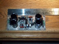
tobias_svensk said:nice Russ!
And how do they sound compare to all your others?
Are they between Mauros and all the rest?
Thanks Tobias! They sound very good, better than Any NI chipamp I have yet to hear, but Mauro's REF is a very high mark to try to exceed. I cannot say this is better, that would be foolish, but I would venture to say it is as good or better than most.
It is dead silent, no humm no hiss.
Damn! that's nice Russ
I'll have to finish mine to sometime , have't decided if i'm going for a unreg. or lm338 reg. PSU yet though. I have eight 10000uF 50V that I was thinking to use, dual PSU four big caps on each. I wonder if a CRC like 10000uF+1ohm(or something)+10000uF would be better than a 10000uF+10000uF, but maybe a CRC is better on a class A amp.? when you have like constant current thru the PSU.
I'll have to finish mine to sometime
, have't decided if i'm going for a unreg. or lm338 reg. PSU yet though. I have eight 10000uF 50V that I was thinking to use, dual PSU four big caps on each. I wonder if a CRC like 10000uF+1ohm(or something)+10000uF would be better than a 10000uF+10000uF, but maybe a CRC is better on a class A amp.? when you have like constant current thru the PSU.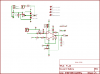
The male fastons come in dirrerent thicknesses .020 and .032 the thinker onse are better, but a little harder to get the connector on. What you can do is use a small flathead screwdriver (or some suitable substitute) and open up the female connector slightly.
Myself, I have never had any issues getting my connectors on or off without modification. You want them to fit tight, as you get better electrical contact.
Myself, I have never had any issues getting my connectors on or off without modification. You want them to fit tight, as you get better electrical contact.
- Status
- This old topic is closed. If you want to reopen this topic, contact a moderator using the "Report Post" button.
- Home
- Amplifiers
- Chip Amps
- My NI chipamp Mark-II - Mr. Ed :)