Hi,
Can someone talk me through this? I'm very new to this electronics things and I would like a little help wiring my toroidal transformer into the power supply so I don't electrocute myself. I'm using an avel 250 25v transformer from parts express and BrianGT's snubberized power supply, a simple 3 prong AC Chassis plug, and a simple fuse. So... can someone help me wire this thing.
The transformer has 8 wires and this is the schematic on the side:
Blue -
Black - 0v
Gray - 2x115v
Red - 25v / 5.00A
Violet -
Orange - 0v
Brown -
Yellow - 25v / 5.00A
Where do I connect each of these wires? I'm not sure where to get a straightforward description.
Thanks,
Alex
Look a little like this?
I also happen to have an Avel torroid from Partsexpress and one of Brian's Snubberized PSUs (and live in Seattle for that matter). I haven't done the final wiring on mine yet since I'm still fabricating the chassis.
I believe you need to wire the blue and violet to neutral, grey and brown to live, and then just wire up each of the 25v pairs to the terminals on the PSU. I'm a noob so I could be off, but I'm sure someone will correct me.
Good luck
An externally hosted image should be here but it was not working when we last tested it.
I also happen to have an Avel torroid from Partsexpress and one of Brian's Snubberized PSUs (and live in Seattle for that matter). I haven't done the final wiring on mine yet since I'm still fabricating the chassis.
An externally hosted image should be here but it was not working when we last tested it.
I believe you need to wire the blue and violet to neutral, grey and brown to live, and then just wire up each of the 25v pairs to the terminals on the PSU. I'm a noob so I could be off, but I'm sure someone will correct me.
Good luck
Is this right?
Thanks for the help and thanks for the link homer09. Here's a test run. I need to put the fuse in line with the grey wire, right?
Velmeran42, email me, I'd like to ask a question or two about your chassis design. amorrow -((at))- u . washington . edu
Thanks for the help and thanks for the link homer09. Here's a test run. I need to put the fuse in line with the grey wire, right?
Velmeran42, email me, I'd like to ask a question or two about your chassis design. amorrow -((at))- u . washington . edu
Attachments
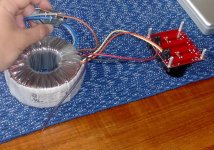
not quite - tie your blue and violet wires together. connect them to your fuse and the fuse to the hot lead of the IEC input (put a switch in this line unless you want to be on all the time) connect your gray and brown wires together and then to the cold side of your IEC.
blue
. >--- fuse --- switch ---hot lead
violet
gray
. >-----cold lead
brown
Use insulated terminals to make the connections, as a soldered joint could potentially fail and allow the hot lead to contact the chassis.
blue
. >--- fuse --- switch ---hot lead
violet
gray
. >-----cold lead
brown
Use insulated terminals to make the connections, as a soldered joint could potentially fail and allow the hot lead to contact the chassis.
 Dont connect what your showing in the picture!
i hope my picture is clear.
Now if make sure your power cable is also wired correctly. your fuse should be inline with the right hole in your wall socket (the smaller one, its smaller because its the hot, so your finger doesnt fit as easily
 )
)connect your power plug to your chasis, dont plug to the wall, and check with a DMM that there is a connection between the fuse and the hot prong, this is very important, a fuse inline with neutral is useless.
On my picture,
H is Hot
N is Neutral
G is Ground (connected to the star ground, not to your transformer!)
Notice the lines over the AC1 and AC2, these are like on Brian's board, match them.
For best noise reduction, twist together the red&black, orange&yellow, blue&grey, brown&purple. Make sure there is no electrical contact between twisted wires as they will cause a short.
If you have a doubt about anything, ask, this could get ugly if you dont. maybe even take another picture with everything wired right before you plug in for the first time.
EDIT: i see i took too long to make my picture and u got your answers already...

Attachments
- Status
- This old topic is closed. If you want to reopen this topic, contact a moderator using the "Report Post" button.
- Home
- Amplifiers
- Chip Amps
- Wiring an Avel Transformer to a BrianGT PS - need help