IMHO seems this all seems errr ....redundant.
If you don't understand the importance of impedance matching different parts of the system, I guess that an active buffer/pre could seem superfluous (or redundant if you prefer).
As Filholder says, it does to some extent depend on what sort of sound that you like but IMHO, the sound is preferable with an active stage before the GC's (and class-T amps)!

Hey Russ,
On the Twisted Pear website do you have a feature list of the Kookaburra? I see a parts list, but it would be nice to have a short explanation of the design and purpose of the components or feature list so people can make comparisons. (or a thread to point me to the preamp, I can't find it for some reason)
On the Twisted Pear website do you have a feature list of the Kookaburra? I see a parts list, but it would be nice to have a short explanation of the design and purpose of the components or feature list so people can make comparisons. (or a thread to point me to the preamp, I can't find it for some reason)
New thread for yardbird
The yardbird design is at this thread:
http://www.diyaudio.com/forums/showthread.php?s=&threadid=68406
The yardbird design is at this thread:
http://www.diyaudio.com/forums/showthread.php?s=&threadid=68406
Member
Joined 2003
Somewhere in this thread, Carlosfm posted his preamp design for a OPA627. Besides using different resistor values, and a 2k "class A biasing resistor", I noticed a 330nF capacitor between +V and -V. What would be the idea behind this capacitor? Anyways, I've added the capacitor to my Freebird, and I can't say that I notice much difference at all. I wish I had an oscilloscope so I could do some actual measurements though  .
.
I remember when I did my thesis for school, I had a very bad noise in the circuit which was probably due to a poor ground circuit on the PCB. Anyway my advisor told me to put a small capactor between +V and -V and magically all the noise had vanished. I can't for the life of me remember why he said to do that, and I was hoping someone here would know?
.I remember when I did my thesis for school, I had a very bad noise in the circuit which was probably due to a poor ground circuit on the PCB. Anyway my advisor told me to put a small capactor between +V and -V and magically all the noise had vanished. I can't for the life of me remember why he said to do that, and I was hoping someone here would know?
DcibeL said:[B
I remember when I did my thesis for school, I had a very bad noise in the circuit which was probably due to a poor ground circuit on the PCB. Anyway my advisor told me to put a small capactor between +V and -V and magically all the noise had vanished. I can't for the life of me remember why he said to do that, and I was hoping someone here would know? [/B]
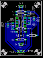
Probably because the active component was not well bypassed in the first place. This circuit is very well bypassed.
 Also, the signal and power grounding is solid.
 Mick_F said:What is the use of the Cc capacitor? Are you sure it will not be a problem when DC comes in?
Mick
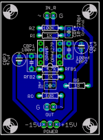
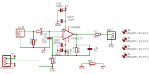
The CC( compensation cap) capacitor is optional, and is only really needed if you are using a very high speed/high SR opamp in very ow gain, like an OPA637 or OPA228 which otherwise would not be stable.
For DC you would put a decoupling cap at the volume pot wiper. There is none on the PCB an it is optional, most sources do not have DC.
This is a well proven design, quite a few here have built it.
The resistor values are all just suggestions you can use quite a broad range of values.
The important resistors are RFB1 and RFB2.
Gain is set by the following formula:
G=1+(RFB1/RFB2);
Cheers!
Russ
Member
Joined 2003
Cool, then there is no harm done by adding it in there.Russ White said:Probably because the active component was not well bypassed in the first place. This circuit is very well bypassed.
I have noticed absolutely no DC on the ouput of the 627. I removed the coupling caps on my source which resulted in 3.4mV of DC. There is also 3.4mV of DC on the output of the 627 which is great because now there is only one coupling cap in my entire system.
- Status
- This old topic is closed. If you want to reopen this topic, contact a moderator using the "Report Post" button.
- Home
- Amplifiers
- Chip Amps
- The "Freebird" ultra clean ultra simple preamp design