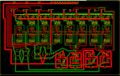
Here is a rather large pic of the pcb:
And attached is the ExpressPCB File so anyone can suggest some changes.
(SCH and partial design credits to bigmike216)
An externally hosted image should be here but it was not working when we last tested it.
And attached is the ExpressPCB File so anyone can suggest some changes.
(SCH and partial design credits to bigmike216)
Attachments
ctardi said:The power leads are 0.1", what should they be?
I'm not sure how much capitance I should have, can you make any suggestions?
Copper is free when getting a PCB made, remember it has to be etched or milled off the insulating material. Make the power traces as wide as you can.
Take a look at the LM4870 application note for a suggested board layout...study the power and grounding portions.
Each amplifier chip will typically require a large electrolytic (when I made my boards I chose 680uF) and a smaller value ceramic, say .1uF. I threw in a smaller 10uF electrolytic for good measure. The .1uF should be as physically close to the chips as you can make them, followed by the 10uF, then the large bypass.
Check out the following thread for pics of my board.
http://www.diyaudio.com/forums/showthread.php?s=&threadid=59235
Scott

Indeed. For simple graphics like that you should compress to PNG (or GIF if you can't do PNG). Trim off all the excess (task bar, tile bar and anything else that doesn't interest us) and convert down to 256 or 16 colours before compressing. This will give you much smaller size than JPG and yet also better quality. JPG should only be used for high-colour, complex images like photos.
ctardi said:Well, if i could edit it, I would. But i can't seem to find the edit button...
The larger caps, 1,3,and the two unnumbered are 3300uf. They are followed by a 0.1uf. I think that will be plenty, no? I'll also work on the power traces.
Maybe? Inductance is a function of cross sectional area and length. The thinner the traces, and longer the more inductance. The National parts, with their high open loop bandwidth are susceptible to such inductance, which is why the data sheets says place the bypass capacitance at the part, physically as close to the pins as possible. You should take that very seriously, that capacitance needs to be as close to the pins as physically possible using a circuit board.
I think you'd be much better off with distributing those capacitors, or making multiple boards, one for each amp.
Scott
I guess i didn't mention, nor did anyone ask, but the chips are from TI, and consist of opa549, opa637, drv134, and buf634.
Also, can someone double check the power section in the botom right, i'm not too clear on how it works, and didn't design it, so am not too sure on where exactly the diodes will get solderd, as I am using MURD620CT's.
Also, can someone double check the power section in the botom right, i'm not too clear on how it works, and didn't design it, so am not too sure on where exactly the diodes will get solderd, as I am using MURD620CT's.
ctardi said:I guess i didn't mention, nor did anyone ask, but the chips are from TI, and consist of opa549, opa637, drv134, and buf634.
Also, can someone double check the power section in the botom right, i'm not too clear on how it works, and didn't design it, so am not too sure on where exactly the diodes will get solderd, as I am using MURD620CT's.
The grounding, and bypass guidelines laid out in the National data sheet are just as valid for TI parts, in fact for all analog circuitry. They aren't chip specific, just good practice.
Scott
ctardi said:Well, if i could edit it, I would. But i can't seem to find the edit button...
you still can, this picture is linked from an outside source (presumably your webspace) so just upload a much more compressed picture with the same file name. or to avoid having to use a jpeg, upload a blank tiny jpeg to replace, and repost a properly compressed picture (and possibly updated) in a new post.
ctardi said:That picture is hosted on diyaudio as an attachment.
no it isnt. it is hosted on
'http://members.shaw.ca/ctardi/ampboard.JPG'
pictures hosted by diyaudio.com appear as thumbnails attached to the bottom of the post, precisely to avoid this kind of thing.
if you do not believe me, rename ampboard.JPG on your webspace to something else, refresh this thread (after flushing cache) and your picture will be gone.
EDIT: what is attached is your zip file, and that is no problem. your picture cannot also be attached, as only one attachment per post is allowed.
It can now be viewed at http://members.shaw.ca/ctardi/ampboard.bmp
An externally hosted image should be here but it was not working when we last tested it.
Originally posted by ctardi ... but i did stay at a holiday inn express last night.")
Is that the local brothel?

Hi,
To reiterate what has already been said, you really need local decoupling on your amplifers or they are very likely to go unstable especially at clip.
Other than that all of your return currents for the amps share the same path and it is not very thick. You are likely to get crosstalk in this path. The PSU seems to be set up with the center of C1 and C3 as the earth star point but not all of the return paths go to that point. This will cuase extra distortion and hum. You should connect the center of the caps to the earth from your transformer. This is the center tap on the windings in most designs.
I would recommend connecting the earths for the ouputs directly to the center of the capacitors rather than running them round the outside of the board. The wire will be much lower impedance than a track and its not shared by all the amplifers. Either that or use seperate return paths for each aplifer and run them back close to the amp this will minimise the current loop.
I can't really quite work out what is going on without a schematic but it looks like your feedback paths, if that is what they are, go round the outside of the amplifers. If this is what they are this will almost certainly cause instability. It would be much better to treat each of the amplifers as a seperate desiagn rather than commoning up all the power lines and making the routing of the ofther signals have to go round. At the very least keep the feedback path local to the amplifer.
The power rail from C1 looks like it goes through a single via this is not a good idea as it will be resistive. better to redesign so it can stay on the same layer all the way to the output stage.
hope this is of some help.
Regards,
Andrew
- Status
- This old topic is closed. If you want to reopen this topic, contact a moderator using the "Report Post" button.
- Home
- Amplifiers
- Chip Amps
- My Amp