So, I finally constructed my brian gt lm3875 chip amp. I made sure that my power supply was working properly first. Sure enough, +30VDC on the +'ve rail, -30VDC on the -'ve rail. I wired up the amp boards, and finally plugged the thing in. The fuse blew in less than 5 seconds.
I double checked my wiring and every thing seemed to be in order. There were no obvious shorts, and I poked around with my meter on circuit test mode to see if i could find anything unusual. I couldn't.
A few thoughts:
-i have a 24V (5A) lamp connected in parallel with my 22V-0V-22V toroid's secondaries (beween 0 and one 22 wire). Could this have pushed the current limits of my 2A slow blow fuse?
-is a 2A fuse appropriate from my setup?
-my grounding arangement might be a bit wonky.. I dont see how this would cause a problem (other than maybe hum), but my inputs are grounded through the chasis, due to the way they are attached to the case.
-My heatsink, as well as the screw that holds the chip on to it, are grounded. I have the insullated vesion of the chip, so i dont think that should be a problem. Maybe the threads of the screw cut through the insulation?
Can you guys suggest anything that I should check for, before I pop another fuse in there and try again? Thanks for your help.
StalfoS said:
-i have a 24V (5A) lamp connected in parallel with my 22V-0V-22V toroid's secondaries...
Why? That's over 100W!
When using variac, it's worth mentioning that DC offset goes initially pretty high (to about 2V or so) and then its value settles down to almost 0V when supply voltage increases.
Sure, variac is the best in such cases, but don't get discouraged when it's not available")
And don't forget to wear glasses, when running new circuits for the first time
Sure, variac is the best in such cases, but don't get discouraged when it's not available
And don't forget to wear glasses, when running new circuits for the first time
Thanks fro the responses guys...
Im pretty sure that PG+ an V+ are not shorted, nor PG- and V- for that matter.
I do not have acces to much in the way of test equipment, so use of any sort of variable power supply is out the window..
I picked up my toroid a while ago, so i can't imediately remeber how big it is. It is probably beween 200-300 VA, definately no more than 300. I will try to find out.
Perhaps I will try using a 4A fuse and see if I have any more luck.
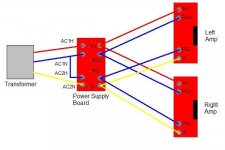
StalfoS said:Does the attached file make sense for my wiring arrangement?
I notice that there is 20V dc between PG+ and PG-... does this make any sense at all?
nope. you are using your center-tapped (assuming from how you drew your diagram) transfo as a true dual secondary transfo.

refer to brian's user guide, there is a section explaining how to wire center-taps to his rectifier pcbs.
This wiring schematic will blow fuse. CT tranny ground not wired to rectifier board.StalfoS said:Does the attached file make sense for my wiring arrangement?
I found this thread which may be useful for you.
http://www.diyaudio.com/forums/showthread.php?postid=627150#post627150
http://www.diyaudio.com/forums/showthread.php?postid=627150#post627150
- Status
- This old topic is closed. If you want to reopen this topic, contact a moderator using the "Report Post" button.
- Home
- Amplifiers
- Chip Amps
- Blown fuse!!!